| |
|
|
|
|
|
|
|
|
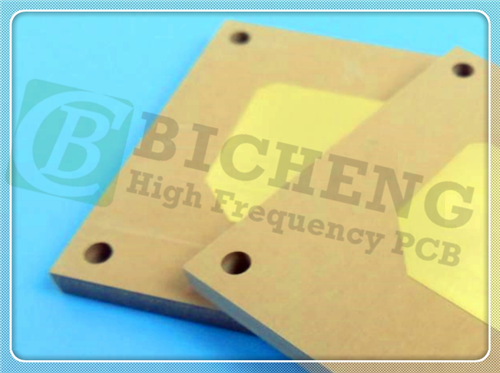
DK4.5 60mil 1.524mm TMM4 High Frequency PCB Double-layer Rogers RF PCB with Immersion Gold for Antennas |
|
|
(Printed Circuit Boards are custom-made products. The picture and parameters shown are for reference only.) |
|
|
|
|
|
General Description |
|
|
This product is a double-layer RF PCB constructed on a Rogers TMM4 substrate with a thickness of 60mil. The board features a single NPTH (non-plated through hole) and utilizes 0.5oz base copper, which is plated up to 1oz for enhanced conductivity. The surface finish on the pads is immersion gold, while the board does not include solder mask or silkscreen printing for a clean, minimalist design. The top layer contains the signal tracks, while the entire bottom layer is fully covered with copper to provide effective shielding.
Manufactured in compliance with IPC Class II standards, each board undergoes 100% electrical testing to ensure optimal performance and reliability before shipment. For secure delivery, every set of 25 boards is vacuum-packed, ensuring protection during transit. This design is ideal for high-frequency applications requiring precision and durability. |
|
|
|
|
|
PCB Specifications |
|
|
PCB SIZE |
90 x 90mm=1up |
BOARD TYPE |
Double sided PCB |
Number of Layers |
2 layers |
Surface Mount Components |
YES |
Through Hole Components |
NO |
LAYER STACKUP |
copper ------- 17um(0.5 oz)+plate TOP layer |
|
TMM4 1.524mm |
|
copper ------- 17um(0.5 oz) + plate BOT Layer |
TECHNOLOGY |
|
Minimum Trace and Space: |
100 mil / 100 mil |
Minimum / Maximum Holes: |
1.5 mm / 1.5 mm |
Number of Different Holes: |
1 |
Number of Drill Holes: |
1 |
Number of Milled Slots: |
0 |
Number of Internal Cutouts: |
0 |
Impedance Control: |
no |
Number of Gold finger: |
0 |
BOARD MATERIAL |
|
Glass Epoxy: |
TMM4 1.524mm |
Final foil external: |
1.0 oz |
Final foil internal: |
N/A |
Final height of PCB: |
1.6 mm ±0.16 |
PLATING AND COATING |
|
Surface Finish |
Immersion Gold, 89% |
Solder Mask Apply To: |
N/A |
Solder Mask Color: |
N/A |
Solder Mask Type: |
LPI |
CONTOUR/CUTTING |
Routing |
MARKING |
|
Side of Component Legend |
N/A |
Colour of Component Legend |
N/A |
Manufacturer Name or Logo: |
N/A |
VIA |
N/A |
FLAMIBILITY RATING |
94V-0 |
DIMENSION TOLERANCE |
|
Outline dimension: |
0.0059" |
Board plating: |
0.0029" |
Drill tolerance: |
0.002" |
TEST |
100% Electrical Test prior shipment |
TYPE OF ARTWORK TO BE SUPPLIED |
email file, Gerber RS-274-X, PCBDOC etc |
SERVICE AREA |
Worldwide, Globally. |
|
|
|
|
|
|
 |
|
|
|
|
|
Typical Applications: |
|
|
1. Chip testers
2. Dielectric polarizers and lenses
3. Filters and coupler
4. Global Positioning Systems Antennas
5. Patch Antennas
6. Power amplifiers and combiners
7. RF and microwave circuitry
8. Satellite communication systems |
|
|
|
|
|
Our Capability (TMM4) |
|
|
PCB Material: |
Composite of Ceramic, hydrocarbon and thermoset polymer |
Designator: |
TMM4 |
Dielectric constant: |
4.5 ±0.045 (process); 4.7 (design) |
Layer count: |
Single Sided, Double Sided, Multi-layer, Hybrid designs |
Copper weight: |
1oz (35µm), 2oz (70µm) |
Laminate thickness: |
15mil (0.381mm), 25mil (0.635mm), 30mil (0.762mm), 50mil (1.270mm), 60mil (1.524mm), 75mil (1.905mm), 100mil (2.540mm), 125mil (3.175mm), 150mil (3.810mm), 200mil (5.08mm), 250mil (6.35mm), 500mil (12.7mm) |
PCB size: |
≤400mm X 500mm |
Solder mask: |
Green, Black, Blue, Yellow, Red etc. |
Surface finish: |
Bare copper, HASL, ENIG, Immersion tin, Immersion Silver, Pure gold (no nickle under gold), OSP, ENEPIG |
|
|
|
|
|
|
Data Sheet of TMM4 |
|
|
TMM4 Typical Value |
Property |
TMM4 |
Direction |
Units |
Condition |
Test Method |
Dielectric Constant,εProcess |
4.5±0.045 |
Z |
|
10 GHz |
IPC-TM-650 2.5.5.5 |
Dielectric Constant,εDesign |
4.7 |
- |
- |
8GHz to 40 GHz |
Differential Phase Length Method |
Dissipation Factor (process) |
0.002 |
Z |
- |
10 GHz |
IPC-TM-650 2.5.5.5 |
Thermal Coefficient of dielectric constant |
+15 |
- |
ppm/°K |
-55℃-125℃ |
IPC-TM-650 2.5.5.5 |
Insulation Resistance |
>2000 |
- |
Gohm |
C/96/60/95 |
ASTM D257 |
Volume Resistivity |
6 x 10⁸ |
- |
Mohm.cm |
- |
ASTM D257 |
Surface Resistivity |
1 x 10⁹ |
- |
Mohm |
- |
ASTM D257 |
Electrical Strength(dielectric strength) |
371 |
Z |
V/mil |
- |
IPC-TM-650 method 2.5.6.2 |
Thermal Properties |
Decompositioin Temperature(Td) |
425 |
425 |
℃TGA |
- |
ASTM D3850 |
Coefficient of Thermal Expansion - x |
16 |
X |
ppm/K |
0 to 140 ℃ |
ASTM E 831 IPC-TM-650, 2.4.41 |
Coefficient of Thermal Expansion - Y |
16 |
Y |
ppm/K |
0 to 140 ℃ |
ASTM E 831 IPC-TM-650, 2.4.41 |
Coefficient of Thermal Expansion - Z |
21 |
Z |
ppm/K |
0 to 140 ℃ |
ASTM E 831 IPC-TM-650, 2.4.41 |
Thermal Conductivity |
0.7 |
Z |
W/m/K |
80 ℃ |
ASTM C518 |
Mechanical Properties |
Copper Peel Strength after Thermal Stress |
5.7 (1.0) |
X,Y |
lb/inch (N/mm) |
after solder float 1 oz. EDC |
IPC-TM-650 Method 2.4.8 |
Flexural Strength (MD/CMD) |
15.91 |
X,Y |
kpsi |
A |
ASTM D790 |
Flexural Modulus (MD/CMD) |
1.76 |
X,Y |
Mpsi |
A |
ASTM D790 |
Physical Properties |
Moisture Absorption (2X2) |
1.27mm (0.050") |
0.07 |
- |
% |
D/24/23 |
ASTM D570 |
|
3.18mm (0.125") |
0.18 |
|
|
|
|
Specific Gravity |
2.07 |
- |
- |
A |
ASTM D792 |
Specific Heat Capacity |
0.83 |
- |
J/g/K |
A |
Calculated |
Lead-Free Process Compatible |
YES |
- |
- |
- |
- |
|
|
|
|
|
|
|
|
|
|
|
|
|
|
|
Hot Tags:
2-Layer Rogers RF PCB |
Rogers TMM4 Laminate |
TMM4 High-Frequency PCB |
60mil 1.524mmTMM4 PCB |
TMM4 Antennas PCB |
|
|
|
