|
|
|
|
|
|
Copper Foil Classifications and Copper Roughness Specifications for Rogers High Frequency Materials
|
|
|
|
|
|
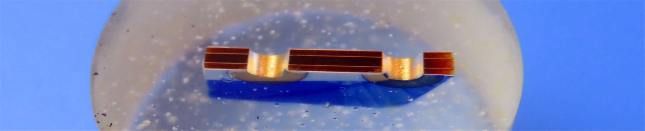
Copper foils designed for diverse range of high-frequency circuit substrates are optimized for peak performance in highly reliable applications. Various types of copper foil are available, differing in weight (thickness). Understanding these differences is crucial for selecting the appropriate copper foil for specific applications or environmental conditions. |
|
|
|
|
|
Two types of Copper Foil Manufacturing |
|
|
(I) Standard Electrodeposited Copper |
|
|
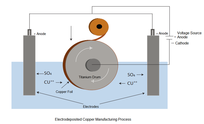
In the electrodeposition process, copper foil is formed on a titanium rotating drum from a copper solution connected to a DC voltage source. The cathode is fixed to the drum while the anode is submerged in the copper electrolyte solution. When an electric field is applied, copper deposits onto the drum as it rotates slowly. The surface of the drum side is smooth, whereas the opposite side is rough. A slower drum speed results in thicker copper deposits, and vice versa. Copper is attracted and accumulates on the cathode surface of the titanium drum. The matte and drum sides of the copper foil undergo different treatment cycles to prepare the copper for PCB fabrication. These treatments enhance the adhesion between the copper and the dielectric interlayer during the copper cladding lamination process. Additionally, the treatments serve as anti-tarnish agents, helping to slow down the oxidation of copper. |
|
|
|
|
|
|
|
|
(II) Rolled Copper |
|
|
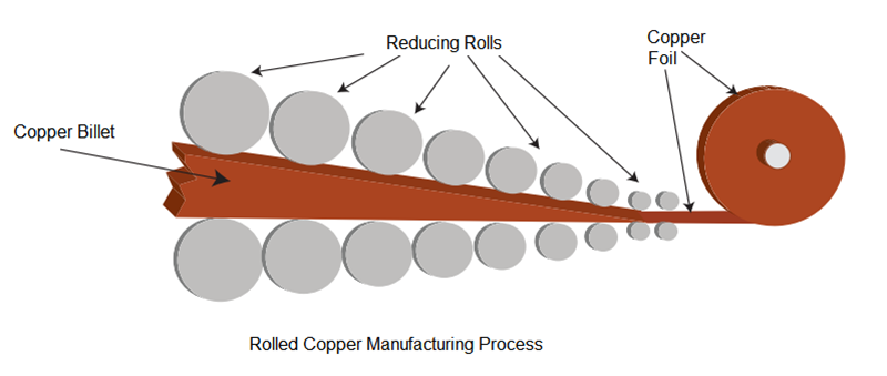
Rolled copper is produced through a series of cold rolling processes that reduce its thickness and increase its length, beginning with a billet of pure copper. The smoothness of the surface is influenced by the condition of the rolling mill. |
|
|
|
|
|
|
|
|
Copper Foil Roughness Measurements |
|
|
Surface roughness can be measured using both mechanical and optical methods. Many sources report the ※Rz§ (peak-to-valley) profile obtained from a mechanical profilometer. However, based on our experience, the Sq (RMS) profile measured by white light interferometry of the treated side of copper foil correlates most effectively with conductor losses. |
|
|
|
|
|
The roughness of standard copper foil (STD) is approximately 7-8μm, that of reverse-treated copper foil is around 4-6μm, low roughness copper foil has a roughness of about 3-4μm, and ultra-low roughness copper foil has a roughness of approximately 1.5-2μm. |
|
|
|
|
|
According to the roughness of the ED copper foil, it can be further subdivided into the following types: |
|
|
|
|
|
(i) STD: Standard Electrodeposited copper foil |
|
|
|
|
|
(ii) Reverse Treated ED Copper Foil (RTF) |
|
|
Reverse-treated foil, also known as reverse-treated copper foil, Double treated copper foil, where both sides undergo roughening treatment. Reverse treated foils involve the processing of the smooth side of electrodeposited copper. This treatment adds thin coatings that enhance adhesion of the base foil to dielectrics and increase corrosion resistance, resulting in a rougher shiny side. During the production of circuit board panels, the treated side of the copper is laminated to the dielectric material. The increased roughness of the treated drum side leads to superior adhesion to the dielectric, providing a significant advantage over standard ED copper. The matte side requires no additional mechanical or chemical treatment before applying photoresist, as it is already sufficiently rough for effective laminate resist adhesion.?The roughness generally ranges between 2-4 μm. |
|
|
|
|
|
(iii) Low Profile?Copper Foil(LP) |
|
|
Low-profile copper foil, featuring a low roughness surface, suitable for high-speed boards. |
|
|
The original foil of general copper foil has very rough microcrystals, appearing as large columnar crystals. The edges of its sliced cross-section have large undulations. In contrast, the crystals of low-profile copper foil are very delicate (below 2 μm), forming equiaxed grains without columnar crystals, presenting a layered crystal structure with flat edges. The surface roughness is low. According to actual measurements, the average roughness (Ra) of ultra-low-profile electrolytic copper foil is 0.55 μm (general copper foil is 1.40 μm). The maximum roughness is 5.04 μm (compared to 12.50 μm for general copper foil). |
|
|
|
|
|
For LoPro? copper, a thin layer of adhesive is applied to the reverse treated side of the copper. This physical layer enhances bonding. Similar to reverse treated electrodeposited copper, the adhesive-treated side bonds effectively to the dielectric layer, ensuring improved adhesion. Rogers* RO4000 series materials are available laminated with LoPro copper foil. |
|
|
|
|
|
(iv) HTE: High temperature elongation electrodeposited copper foil, abbreviated as HTE copper foil, maintains excellent ductility at high temperatures (180°C). For copper foils with thicknesses of 35μm and 70μm, the elongation at high temperatures (180°C) should be maintained at 30% or more of the elongation at room temperature. Also known as high ductility copper foil (HD copper foil). HTE foils are manufactured by annealing ED copper at a high temperature. The roughness generally ranges between 4-8 μm. |
|
|
|
|
|
(v) VLP: Very low-profile copper foil |
|
|
|
|
|
(vi) ULP (Ultra Low Profile), The roughness generally ranges between 1-2 μm. |
|
|
|
|
|
(vii) HVLP: High Velocity Low Profile copper foil, used in high-frequency and high-speed board applications. The roughness generally ranges between 0.5-1 μm. |
|
|
|
|
|
(viii) UTF: Ultra-thin copper foil, copper foil thinner than 9μm. Copper foil used for printed circuit boards with a thickness below 9μm. Typically, the copper foil used in the outer layers of multilayer boards is over 12μm, while for the inner layers of multilayer boards, it is over 18μm. Copper foil below 9μm?is employed in the production of printed circuit boards with fine circuits. Due to the difficulty in handling extremely thin copper foil, a carrier is generally used for support. Carriers can include copper foil, aluminum foil, organic thin films, and others. |
|
|
|
|
|
(ix) RCC: Resin-coated copper foil, typically used for HDI board lamination.
This product involves applying one or two layers of a special resin solution (typically epoxy resin) onto the roughened surface of thin electrolytic copper foil (generally less than or equal to 18μm?in thickness). Through processing in an oven to remove solvents, the resin reaches a semi-cured B-stage form. The thickness of the copper foil used in RCC typically does not exceed 18μm, with 12μm?being commonly used, and the resin layer thickness generally falls between 40-100μm. In the production process of laminated multi-layer boards, RCC serves to replace both traditional semi-cured sheets and copper foil, acting as an insulating medium and conductor layer. It allows for the creation of laminated multi-layer boards through a process similar to traditional multilayer board pressing, where it is pressed and formed together with the core board, facilitating the manufacturing of laminated multi-layer boards. |
|
|
|
|
|
(x)Resistive Copper |
|
|
The matte side of the electrodeposited copper is coated with a metal or alloy that serves as a resistive layer. The subsequent step involves roughening this resistive layer using nickel particles. |
|
|
|
|
|
Crystalline Structure |
|
|
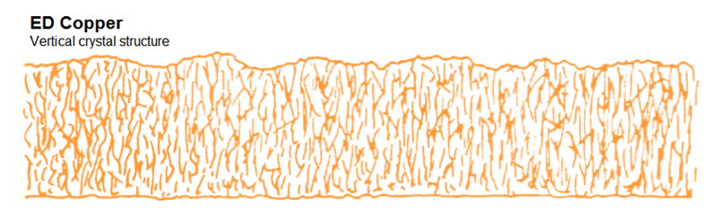
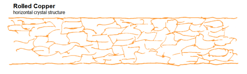
In electrodeposited copper, the crystals generally grow lengthwise along the Z-axis of the foil. A polished cross-section of electrodeposited copper foil typically resembles a picket fence, featuring long crystal boundaries that are perpendicular to the foil plane. In contrast, the crystals of rolled copper are fractured and compressed during the cold rolling process. As a result, they are smaller than those of electrodeposited copper and exhibit irregular, spherical shapes that are nearly parallel to the foil plane. |
|
|
|
|
|
|
|
|
|
|
|
|
|
|
|
|
|
Appendix: |
|
|
| |
Foil Type |
Weight or Thickness |
Surface Roughness
Sq (μm) |
Products |
Dielectric
Side |
Top
Side |
Rolled |
1 oz (35 μm) |
0.4 |
0.3 |
XtremeSpeed RO1200, RO3003, RO3035, RT/duroid® 5870, 5880,
6002, 6202, CLTETM, CLTE-ATTM, CLTE-XTTM, CLTE-MWTM, CuClad®217,
CuClad 233, CuClad 250, DiClad®527, DiClad®870, DiClad®880,
IsoClad®917, IsoClad 933 |
½ oz. (18 μm) |
0.4 |
0.3 |
Electrodeposited |
2 oz (70 μm) |
1.6 |
0.4 |
TC350TM, TC600TM , AD250TM, AD255TM, AD300TM, AD350TM |
1 oz (35 μm) |
1.5 |
0.4 |
½ oz. (18 μm) |
1.6 |
0.4 |
2 oz (70 μm) |
3.0 |
0.4 |
CuClad 217, CuClad 233, CuClad 250, DiClad 527, DiClad 870, DiClad
880, IsoClad 917, IsoClad 933, CuClad, CLTE, CLTE-AT, CLTE-XT, CLTE-MW,
AD1000TM |
1 oz (35 μm) |
1.7 |
0.4 |
½ oz. (18 μm) |
1.5 |
0.4 |
1 oz (35 μm) |
2.4 |
0.4 |
RO3003, RO3006, RO3010, RO3035, RO3210, RT/duroid 5870, 5880,
5880LZ, 6002, 6035HTC (not available with 1/4 oz cu) , 6202, 6006,
6010.2LM,TMM® 3,4, 6,10, 10i, 13i |
½ oz. (18 μm) |
2.0 |
0.4 |
¼ oz. (9 μm) |
1.3 |
0.4 |
4 oz (140 μm) |
3.0 |
0.4 |
92MLTM, 92ML StaCool |
3 oz (105 μm) |
3.2 |
0.4 |
2 oz. (70 μm) |
3.5 |
0.4 |
KappaTM 438, RO4003C, RO4350B, RO4360G2? RO4533?, RO4534?,
RO4535, RO4730G3? (½ oz & 1 oz only), RO4835TM, 92ML, 92ML
StaCool, CU4000 |
1 oz. (35 μm) |
3.2 |
0.4 |
½ oz. (18 μm) |
2.8 |
0.4 |
1 oz. (35 μm) |
0.5 |
0.4 |
XtremeSpeed RO1200, AD300D-IM AD255C-IM, DiClad 880-IM |
½ oz. (18 μm) |
0.5 |
0.4 |
XtremeSpeed RO1200 |
2 oz. (70 μm) |
- |
0.4 |
RO4835TTM
RO3003G2 (½ oz & 1 oz only) |
1 oz. (35 μm) |
- |
0.4 |
½ oz. (18 μm) |
0.7 |
0.4 |
Electrodeposited
Low Profile
Reverse Treated |
2 oz. (70 μm) |
1.0 |
2.0 |
DiClad 527, DiClad 870, DiClad 880, IsoClad 917, IsoClad 933, CuClad
217, CuClad 233, CuClad 250, CLTE, CLTE-AT, CLTE-XT, CLTE-MW, AD1000,
XtremeSpeed RO1200 (2 oz. only) |
1 oz. (35 μm) |
1.0 |
1.3 |
½ oz. (18 μm) |
1.0 |
0.8 |
2 oz. (70 μm) |
1.0 |
1.8 |
AD250, AD255, AD300, AD350, RT/duroid 6002, 6006, 6010.2LM, 6202,
6002PR, 6202PR, TC350, TC350 Plus, TC600 |
1 oz. (35 μm) |
1.0 |
1.5 |
RT/duroid 6035HTC, 6002, 6006, 6010.2LM, 6202, 6002PR, 6202PR,
AD250, AD255, AD300, AD350, RO3003, RO3006, RO3010, RO3210,
TC350, TC350 Plus, TC600 |
½ oz. (18 μm) |
1.0 |
1.0 |
LoPro® Foil |
1 oz. (35 μm) |
0.9 |
1.3 |
RO4003C, RO4350B, RO4533, RO4534, RO4535, RO4725JXRTM,
RO4730JXR, RO4730G3, RO4830, RO4835, CU4000 LoPro |
½ oz. (18 μm) |
0.9 |
0.8 |
Resistive Foil |
NiCrTicerTCR®
½ oz. (18 μm) |
1.4 |
0.4 |
RO4003C, RO4350B, RO4360G2, RO4835 |
OhmegaPly®
½ oz (18 μm) |
1.7 |
0.4 |
RO4003C |
OhmegaPly
½ oz. (18 μm) |
1.2 |
0.4 |
CuClad 217, CuClad 233, CuClad 250, CLTE, CLTE-XT, Diclad 527, DiClad
870, DiClad 880, IsoClad 917, IsoClad 933, RO3003 , RO3006, RO3010,
RO3035, RO3210, RT/duroid 5870, 5880, 6002, 6202, 6006, 6010.2LM |
Typical Root Mean Square Roughness Values |
|
|
|
|
|
|
|
|