| |
|
|
|
|
|
|
|
|
4-Layer-16mil-Rogers-RO4003C-and-FR4-Hybrid-RF-and-High-Frequency-Circuit-Boards-with-Immersion-Tin |
|
|
|
|
|
(As PCBs are custom - produced goods, the picture and parameters shown are only intended for reference.) |
|
|
|
|
|
Hello Everyone,
Today, we’re diving into two variations of 4-layer high-frequency PCBs, both built on a 16mil core of RO4003C material. The 4-layer design was chosen for its simplicity and cost-effectiveness, making it an ideal solution to explore and penetrate new markets.
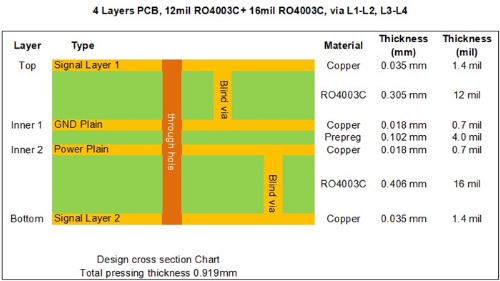
Before we delve deeper, let’s take a look at the stack-up configuration. |
|
|
|
|
|
 |
|
|
|
|
|
Looking at the stack-up, we can observe that the 1st layer to the 2nd layer and the 4th layer to the 3rd layer are constructed using 12mil and 16mil cores of RO4003C, respectively. The fixed thickness of these cores is critical for maintaining the precise electrical length of RF lines on the circuit board. These cores are bonded together using a bonding film, commonly referred to as Prepreg.
Currently, there are two types of Prepreg (PP) materials used in multi-layer high-frequency PCBs: FR-4 dielectric and high-frequency dielectric materials, such as RO4450F, Cuclad 6250, and Taconic’s FastRise-28 (FR-28), among others.
The inner layers feature a copper weight of half an ounce, while the outer layers use 1-ounce copper. Additionally, blind vias are drilled into both cores to ensure optimal connectivity and performance. |
|
|
|
|
 |
|
|
|
|
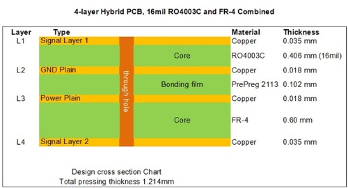
The second board is a hybrid design, combining FR-4 material on layers 3 and 4, while high-frequency signals are routed on the high-frequency substrate layers: L1 and L2. Depending on the specific application requirements, the thickness of both the dielectric material and FR-4 can be customized to achieve optimal performance. |
|
|
 |
|
|
|
|
|
Application |
|
|
The 16mil RO4003C hybrid PCB finds extensive applications across various fields, including modular oscilloscopes, antenna combiners, balanced amplifiers, 4G antennas, and more. Its versatility makes it a reliable choice for high-performance electronic systems. |
|
|
|
|
|
The advantages of 16mil RO4003C hybrid PCB are shown as follows: |
|
|
1. RO4003C maintains a stable dielectric constant across a wide frequency range, making it an excellent choice for broadband applications.
2. Minimizing signal loss in high-frequency applications aligns perfectly with the evolving demands of modern communication technology.
3. By combining RO4003C with cost-effective materials, this hybrid stack-up reduces overall expenses compared to designs using entirely low-loss materials. |
|
|
|
|
|
 |
|
|
|
|
|
RO4003C is available in standard thicknesses of 0.008” (0.203mm), 0.012” (0.305mm), 0.016” (0.406mm), 0.020” (0.508mm), 0.032” (0.813mm), and 0.060” (1.524mm). All these thickness options are stocked in-house, ensuring quick turnaround and reliable supply.
We welcome your inquiries and look forward to serving your needs! |
|
|
|
|
|
Data Sheet of Rogers 4003C (RO4003C) |
|
|
RO4003C Typical Value |
Property |
RO4003C |
Direction |
Units |
Condition |
Test Method |
Dielectric Constant,εProcess |
3.38±0.05 |
Z |
|
10 GHz/23℃ |
IPC-TM-650 2.5.5.5 Clamped Stripline |
Dielectric Constant,εDesign |
3.55 |
Z |
|
8 to 40 GHz |
Differential Phase Length Method |
Dissipation Factortan,δ |
0.0027
0.0021 |
Z |
|
10 GHz/23℃
2.5 GHz/23℃ |
IPC-TM-650 2.5.5.5 |
Thermal Coefficient of ε |
+40 |
Z |
ppm/℃ |
-50℃to 150℃ |
IPC-TM-650 2.5.5.5 |
Volume Resistivity |
1.7 x 10¹⁰ |
|
MΩ.cm |
COND A |
IPC-TM-650 2.5.17.1 |
Surface Resistivity |
4.2 x 10⁹ |
|
MΩ |
COND A |
IPC-TM-650 2.5.17.1 |
Electrical Strength |
31.2(780) |
Z |
Kv/mm(v/mil) |
0.51mm(0.020") |
IPC-TM-650 2.5.6.2 |
Tensile Modulus |
19,650(2,850)
19,450(2,821) |
X
Y |
MPa(ksi) |
RT |
ASTM D 638 |
Tensile Strength |
139(20.2)
100(14.5) |
X
Y |
MPa(ksi) |
RT |
ASTM D 638 |
Flexural Strength |
276
(40) |
|
MPa
(kpsi) |
|
IPC-TM-650 2.4.4 |
Dimensional Stability |
<0.3 |
X,Y |
mm/m
(mil/inch) |
after etch+E2/150℃ |
IPC-TM-650 2.4.39A |
Coefficient of Thermal Expansion |
11
14
46 |
X
Y
Z |
ppm/℃ |
-55℃to288℃ |
IPC-TM-650 2.4.41 |
Tg |
>280 |
|
℃ TMA |
A |
IPC-TM-650 2.4.24.3 |
Td |
425 |
|
℃ TGA |
|
ASTM D 3850 |
Thermal Conductivity |
0.71 |
|
W/M/oK |
80℃ |
ASTM C518 |
Moisture Absorption |
0.06 |
|
% |
48hrs immersion 0.060"
sample Temperature 50℃ |
ASTM D 570 |
Density |
1.79 |
|
gm/cm3 |
23℃ |
ASTM D 792 |
Copper Peel Stength |
1.05
(6.0) |
|
N/mm
(pli) |
after solder float 1 oz.
EDC Foil |
IPC-TM-650 2.4.8 |
Flammability |
N/A |
|
|
|
UL 94 |
Lead-free Process Compatible |
Yes |
|
|
|
|
|
|
|
|
|
|
Hot Tags:
Hybrid High Frequency PCB |
RO4003C FR4 Hybrid PCB |
16 Mil Hybrid RF Circuit Boards |
Hybrid Immersion Tin Circuit Boards PCB |
16 Mil Mutilayer4-Layer Hybrid PCB |
|
|
|
