| |
|
|
|
|
|
|
|
|
20mil Rogers RO4003C PCB and 0.75mm FR 4 Hybrid Multi-layer PCB Precision Engineered for RF Applications |
|
|
|
|
|
(As PCBs are custom - produced goods, the picture and parameters shown are only intended for reference.) |
|
|
|
|
|
Hello everyone,
Warm greetings!
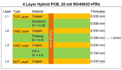
Today, we’ll discuss a 4-layer hybrid PCB constructed using 20mil RO4003C and FR-4 PCB materials. |
|
|
|
|
|
 |
|
|
|
|
|
This PCB features a 4-layer structure. The 1st to 2nd layers consist of a 20mil RO4003C core, serving as the primary wiring layer for signal lines. The 3rd to 4th layers are built on an FR-4 core, with both cores bonded together using 0.2mm prepreg. Each layer is interconnected via plated through holes, and both inner and outer layers have a copper weight of 1 ounce. This design ensures a cost-effective solution without compromising performance.
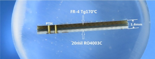
Now, let’s examine its micro-section chart. |
|
|
|
|
 |
|
|
|
|
On the left, you can see the plated through-hole (PTH). The lower section, from Layer 1 to Layer 2, is made of high-frequency material, while the upper part consists of glass fiber material. The finished board thickness is 1.6mm.
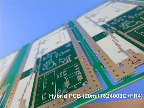
The solder mask and silkscreen colors are the widely used green and white, respectively. The surface finish on the pads is immersion gold. |
|
|
|
|
|
 |
|
|
|
|
|
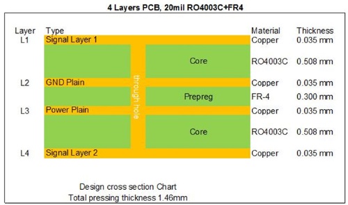
Next, we introduce another variant of the 20mil RO4003C hybrid PCB. This design utilizes two cores of 20mil RO4003C material. |
|
|
 |
|
|
|
|
|
The 20mil RO4003C hybrid PCB has a wide range of applications, including LNAs (Low Noise Amplifiers), optical couplers, balanced amplifiers, duplexers, and more.
The advantages of the 20mil RO4003C hybrid PCB are highlighted in the following three key points:
1. Stable Dielectric Constant: RO4003C maintains a consistent dielectric constant across a broad frequency range, making it an excellent choice for broadband applications.
2. Reduced Signal Loss: It minimizes signal loss in high-frequency applications, aligning with the advanced requirements of modern communication technology.
3. Cost Efficiency: By combining RO4003C with other materials, it offers a cost-effective solution compared to stack-ups using entirely low-loss materials, without compromising performance. |
|
|
|
|
|
Our PCB Capability (Hybrid Design) |
|
|
PCB Type: |
Hybrid PCB, Mixed PCB |
Hybrid type: |
RO4350B + FR4; |
RO4003C + FR4; |
F4B + FR4; |
RT/duroid5880 + FR4; |
RT/duroid5880 + RO4350B |
RO3000 Series + FR4 |
RT/duroid +FR4 |
Solder mask: |
Green, Red, Blue, Black, Yellow |
Layer count: |
4 Layer, 6 Layer, Multilayer |
Copper weight: |
1oz (35µm), 2oz (70µm) |
PCB thickness: |
1.0-10mm |
PCB size: |
≤400mm X 500mm |
Surface finish: |
Bare copper, HASL, ENIG, Immersion tin, Immersion silver, OSP, ENEPIG, Pure gold |
|
|
|
|
|
|
Presently, the mature mixed pressing materials are as follows:
RO4350B + FR4;
RO4003C + FR4;
F4B + FR4;
RT/duroid5880 + FR4
RT/duroid5880 + RO4350B
Thank you for taking the time to read this. For any RF PCB inquiries, feel free to reach out to us—we’re here to assist you! |
|
|
|
|
|
Appendix: RO4003C Data Sheet |
|
|
RO4003C Typical Value |
Property |
RO4003C |
Direction |
Units |
Condition |
Test Method |
Dielectric Constant,εProcess |
3.38±0.05 |
Z |
|
10 GHz/23℃ |
IPC-TM-650 2.5.5.5 Clamped Stripline |
Dielectric Constant,εDesign |
3.55 |
Z |
|
8 to 40 GHz |
Differential Phase Length Method |
Dissipation Factortan,δ |
0.0027
0.0021 |
Z |
|
10 GHz/23℃
2.5 GHz/23℃ |
IPC-TM-650 2.5.5.5 |
Thermal Coefficient of ε |
+40 |
Z |
ppm/℃ |
-50℃to 150℃ |
IPC-TM-650 2.5.5.5 |
Volume Resistivity |
1.7 x 10¹⁰ |
|
MΩ.cm |
COND A |
IPC-TM-650 2.5.17.1 |
Surface Resistivity |
4.2 x 10⁹ |
|
MΩ |
COND A |
IPC-TM-650 2.5.17.1 |
Electrical Strength |
31.2(780) |
Z |
Kv/mm(v/mil) |
0.51mm(0.020") |
IPC-TM-650 2.5.6.2 |
Tensile Modulus |
19,650(2,850)
19,450(2,821) |
X
Y |
MPa(ksi) |
RT |
ASTM D 638 |
Tensile Strength |
139(20.2)
100(14.5) |
X
Y |
MPa(ksi) |
RT |
ASTM D 638 |
Flexural Strength |
276
(40) |
|
MPa
(kpsi) |
|
IPC-TM-650 2.4.4 |
Dimensional Stability |
<0.3 |
X,Y |
mm/m
(mil/inch) |
after etch+E2/150℃ |
IPC-TM-650 2.4.39A |
Coefficient of Thermal Expansion |
11
14
46 |
X
Y
Z |
ppm/℃ |
-55℃to288℃ |
IPC-TM-650 2.4.41 |
Tg |
>280 |
|
℃ TMA |
A |
IPC-TM-650 2.4.24.3 |
Td |
425 |
|
℃ TGA |
|
ASTM D 3850 |
Thermal Conductivity |
0.71 |
|
W/M/oK |
80℃ |
ASTM C518 |
Moisture Absorption |
0.06 |
|
% |
48hrs immersion 0.060"
sample Temperature 50℃ |
ASTM D 570 |
Density |
1.79 |
|
gm/cm3 |
23℃ |
ASTM D 792 |
Copper Peel Stength |
1.05
(6.0) |
|
N/mm
(pli) |
after solder float 1 oz.
EDC Foil |
IPC-TM-650 2.4.8 |
Flammability |
N/A |
|
|
|
UL 94 |
Lead-free Process Compatible |
Yes |
|
|
|
|
|
|
|
|
|
|
Hot Tags:
| High Performance RO4003C PCB |
4-layer RO4003C Substrate |
20mil Rogers High Frequency PCB |
Rogers RO4003C Datasheet |
Rogers RO4003C Hybrid PCB |
|
|
|
