| |
|
|
|
|
|
|
|
|
12mil 0.305mm 6-Layer Hybrid High Frequency Multilayer PCB RO4003C and FR-4 High Performance Reliable Design |
|
|
|
|
|
(As PCBs are custom - produced goods, the picture and parameters shown are only intended for reference.) |
|
|
|
|
|
Hello everyone,
Warm greetings!
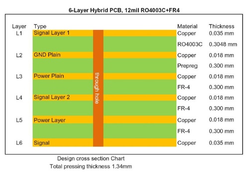
Today, we’re excited to introduce a 6-layer RF PCB constructed with a 12mil RO4003C core and FR-4 material. This board is specifically designed for satellite antenna applications. Below is the detailed stack-up diagram of the board for your reference. |
|
|
|
|
|
|
|
|
|
|
|
From the stack-up diagram, the 12mil core is positioned on the top layer and primarily functions as the signal layer. The core's fixed thickness is critical, as it directly impacts the electrical length of the RF traces on the circuit board. The remaining layers are composed of FR-4 epoxy glass material, with thicknesses comparable to that of the RO4003C core. |
|
|
|
|
The detailed specifications are as follows. |
|
|
Base material: 12mil 0.305mm RO4003C+ Tg170 FR-4
Dielectric constant: 3.38+/-0.05
Layer count: 6 layers
Via type: Through holes
Format: 105mm x 80mm = 1 type = 1 piece
Surface finish: Immersion gold
Copper weight: Outer layer 35μm / Inner layer 18μm
Solder mask / Legend: Green / White
Final PCB height: 1.4 mm
Others: Impedance controlled PCB
Standard: IPC 6012 Class 2
Packing: 20 panels are packed for shipment.
Lead time: 10 working days
Shelf life: 6 months |
|
|
|
|
|
 |
|
|
|
|
|
At present, the mature mixed pressing materials are as follows:
RO4350B + FR4;
RO4003C + FR4;
F4B + FR4;
RT/duroid 5880 + RO4350B RT/duroid 5880 + FR4
Thank you for your reading. You’re welcome to contact us for your RF PCB enquiries. |
|
|
|
|
|
Appendix: Our PCB Capability 2024 |
|
|
Factory Process Capability (2024) |
Substrate Types and Brands |
Standard FR-4, High Tg FR-4, High Frequency Materials, Polyimide/PET flexible Materials |
Shengyi, ITEQ, Isola, Taiwan Union, Rogers Corp. Taconic, Panasonic |
Board Types |
Rigid PCB, Flexible Circuits, Rigid-Flex PCB, Hybrid PCB, HDI PCB |
CCL Model |
High Tg FR-4: S1000-2M, TU-872 SLK, TU-768, IT-180A High CTI FR-4: S1600L, ST115 |
Rogers Corp: RO4350B, RO4003C, RO4725JXR, RO4730G3, RO4360G2, RO4533, RO4534, RO4535, RO4830, RO4835, RO3003, RO3006, RO3010, RO3035, RO3203, RO3210; RT/Duriod 5880; RT/Duriod 5870, RT/Duriod 6002, RT/duroid 6006, RT/Duroid 6010.2LM, RT/duroid 6035HTC; RT/duroid 5880LZ, RT/duroid 6202; TMM3, TMM4, TMM6, TMM10, TMM10i, TMM13i, Kappa 438; AD250C, AD255C, AD300D, AD350A, AD450, AD600, AD1000, TC350; TC600; DiClad 880, DiClad 870, DiClad 527; IsoClad 917, IsoClad 933; CLTE-XT, CLTE-AT, CLTE-MW; CuClad 217, CuClad 233, CuClad 250. |
Taconic: TLF-35; RF-35TC, RF-60A, RF-60TC, RF-35A2,RF-30, RF-35, RF-45, RF-10, TRF-45; TLX-0, TLX-6, TLX-7, TLX-8; TLX-9, TLY-3, TLY-5, TLY-5Z; CER-10; TSM-DS3 |
Wangling: F4BM217, F4BM220, F4BM233, F4BM245, F4BM255, F4BM265, F4BM275, F4BM294, F4BM300;
F4BME217, F4BME220, F4BME233, F4BME245, F4BME255, F4BME265, F4BME275, F4BME294, F4BME300;
F4BTM298, F4BTM300, F4BTM320, F4BTM350;
F4BTME298, F4BTME300, F4BTME320, F4BTME350;
TP300, TP440, TP600, TP615, TP960, TP1020, TP1100, TP1600, TP2000, TP2200, TP2500;
TF300, TF440, TF600, TF960, TF1020, TF1600;
F4BTMS220, F4BTMS233, F4BTMS255, F4BTMS265, F4BTMS294, F4BTMS300, F4BTMS350, F4BTMS430, F4BTMS450, F4BTMS615, F4BTMS1000;
TFA294, TFA300, TFA615, TFA1020;
WL-CT300, WL-CT330, WL-CT330Z, WL-CT338, WL-CT350, WL-CT440, WL-CT615. Dielectric constant ranges DK2.2 DK2.65 DK2.85 DK2.94, DK3.0, DK3.2, DK3.38, DK3.5, DK4.0, DK4.4, DK6.15, DK10.2 |
Maximum Delivery Size |
1200mm x 572 mm |
Minimum Finished Board Thickness |
L≤2L: 0.15mm; 4L: 0.4mm |
Maximum Finished Board Thickness |
10.0 mm |
Blind Buried Holes (Non-crossing) |
0.1mm |
Maximum Hole Aspect Ratio |
15:01 |
Minimum Mechanical Drill Hole Diameter |
0.1 mm |
Through-hole Tolerance |
+/- 0.0762 mm |
Press-fit Hole Tolerance |
+/- 0.05mm |
Non-plated Copper Hole Tolerance |
+/- 0.05mm |
Maximum Number of Layers |
32 |
Internal and External Layer Maximum Copper Thickness |
12Oz |
Minimum Drill Hole Tolerance |
+/- 2mil |
Minimum Layer-to-Layer Tolerance |
+/- 3mil |
Minimum Line Width/Spacing |
3mil/3mil |
Minimum BGA Diameter |
8mil |
Impedance Tolerance |
< 50Ω ±5Ω; ≥50Ω±10% |
Surface Treatment Processes |
Leaded/Lead-free HASL, Immersion Gold, Immersion Silver, Immersion Tin, OSP, ENIG, ENEPIG, Pure gold, Carbon Ink, Peelable Mask, Gold Finger, etc. |
|
|
|
|
|
|
Hot Tags:
High Frequency Multilayer PCB |
Multilayer RO4003C FR-4 PCB |
Hybrid Multilayer PCB Board |
Hybrid Printed Circuit Board |
Roger RO4003C FR-4 PCB |
|
|
|
