| |
|
|
|
|
|
|
|
|
10mil Rogers RO4350B and FR-4 Hybrid Mixed Material PCB with Depth Controlled Drill for GPS Antenna |
|
|
|
|
|
(As PCBs are custom - produced goods, the picture and parameters shown are only intended for reference.) |
|
|
|
|
|
Greetings, everyone.
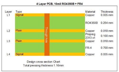
Today, our topic is a 4-layer high-frequency PCB fabricated using 10mil RO4350B in combination with FR-4. A 4-layer design was selected for this board as it offers a good balance between simplicity and cost control, making it an ideal choice for exploring new market opportunities.
First off, let's have a look at how the build-up begins. |
|
|
|
|
|
|
|
|
|
|
|
The 1st to 2nd layers consist of a 10mil RO4350B core material, whose fixed thickness is critical for maintaining the electrical length of RF lines on the circuit board. The remaining layers are made of FR-4 materials, bonded together using semi-cured sheets. The inner layers feature 0.5-ounce copper, while the outer layers use 1-ounce copper.
|
|
|
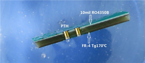
Below is the cross-section image for reference. |
|
 |
|
|
|
Plated through holes (PTH) are used to interconnect all layers, with pads and vias finished in immersion gold for enhanced reliability.
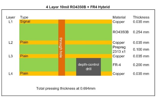
The second board features a unique "hole" design within the structure. Let’s first examine the build-up details. |
|
 |
|
|
|
The 1st and 2nd layers are built on a 10mil core, while the depth-control drill is precisely positioned on the FR-4 side. The entire board has a compact thickness of just 0.7mm. |
|
|
|
 |
|
|
|
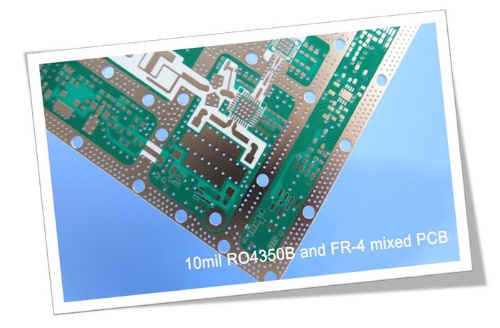
The 10mil RO4350B hybrid PCB has a broad range of applications, including preamplifiers, radar sensors, digital transmitters, and splitter modules; GPS antennas, communication relays, analog transmitters, and 4G antennas; as well as RF transmitters, WiFi amplifiers, RFID systems, and attenuators. |
|
|
|
The advantages of 10mil RO4350B hybrid PCBs: |
|
|
1. Stable Dielectric Constant: RO4350B maintains a consistent dielectric constant across a wide frequency range, making it perfect for broadband applications.
2. Enhanced Signal Integrity: It outperforms stack-ups using only FR4 materials, ensuring superior signal performance.
3. Cost Efficiency: It offers a more economical solution compared to stack-ups made entirely of low-loss materials.
4. Expert Manufacturing Support: From prototyping to mass production, our IATF 16949 (2016), ISO14001 (2015), ISO9001 (2015), and UL-certified facilities ensure top-quality PCBs tailored to your needs. |
|
|
|
|
|
Thank you for your time, and feel free to reach out to us for any RF PCB inquiries—we’re here to assist! |
|
|
|
|
|
Appendix: Our PCB Capability 2022 |
|
|
Parameter |
Value |
Layer Counts |
1-32 |
Substrate Material |
RO4350B, RO4003C, RO4730G3, RO4360G2, RO4533, RO4534, RO4535, RO3003, RO3006, RO3010, RO3035, RO3203, RO3210; RT/Duriod 5880; RT/Duriod 5870, RT/Duriod 6002, RT/Duroid 6010, RT/duroid 6035HTC; TMM3, TMM4, TMM6, TMM10, TMM10i, TMM13i, Kappa 438; TLF-35; RF-35TC, RF-60A, RF-60TC, RF-35A2, RF-45, RF-10, TRF-45; TLX-0, TLX-6, TLX-7, TLX-8; TLX-9, TLY-3, TLY-5; PTFE F4B (DK2.2 DK2.65 DK2.85 DK2.94, DK3.0, DK3.2, DK3.38, DK3.5, DK4.0, DK4.4, DK6.15, DK10.2); AD450, AD600, AD1000, TC350; Nelco N4000, N9350, N9240; FR-4 ( High Tg S1000-2M, TU-872 SLK, TU-768, IT-180A etc.), FR-4 High CTI>600V; Polyimide, PET; Metal Core etc. |
Maximum Size |
Flying test: 900*600mm, Fixture test 460*380mm, No test 1100*600mm |
Board Outline Tolerance |
±0.0059" (0.15mm) |
PCB Thickness |
0.0157" - 0.3937" (0.40mm--10.00mm) |
Thickness Tolerance(T≥0.8mm) |
±8% |
Thickness Tolerance(t<0.8mm) |
±10% |
Insulation Layer Thickness |
0.00295" - 0.1969" (0.075mm--5.00mm) |
Minimum Track |
0.003" (0.075mm) |
Minimum Space |
0.003" (0.075mm) |
Outer Copper Thickness |
35µm--420µm (1oz-12oz) |
Inner Copper Thickness |
17µm--350µm (0.5oz - 10oz) |
Drill Hole(Mechanical) |
0.0059" - 0.25" (0.15mm--6.35mm) |
Finished Hole(Mechanical) |
0.0039"-0.248" (0.10mm--6.30mm) |
DiameterTolerance(Mechanical) |
0.00295" (0.075mm) |
Registration (Mechanical) |
0.00197" (0.05mm) |
Aspect Ratio |
12:1 |
Solder Mask Type |
LPI |
Min Soldermask Bridge |
0.00315" (0.08mm) |
Min Soldermask Clearance |
0.00197" (0.05mm) |
Plug via Diameter |
0.0098" - 0.0236" (0.25mm--0.60mm) |
Impedance Control Tolerance |
±10% |
Surface Finish |
HASL,HASL LF,ENIG,Immersion Tin,Immersion Silver, OSP, Gold Finger, Pure gold plated etc. |
|
|
|
|
|
|
Hot Tags:
10 Mil Multilayer Hybrid PCB |
Mixed Material RO4350B FR-4 PCB |
4 Layer Rogers RO4350B FR4 Hybrid Board |
RO4350B FR4 Hybrids Printed Circuit Board |
Hybrid PCB Mixed Structure PCB |
|
|
|
