| |
|
|
|
|
|
|
|
|
1.0mm-4-Layer-Mixed-Hybrid-PCB-with-High-Quality-4mil-Rogers-RO4350B-and-0.3mm-High-Tg-FR-4 |
|
|
|
|
|
(As PCBs are custom - produced goods, the picture and parameters shown are only intended for reference.) |
|
|
|
|
|
Hello, everyone!
Today, we'll be discussing a 4-layer high-frequency PCB that combines 4mil RO4350B and FR-4 materials. The 4-layer configuration of this PCB was chosen for its simplicity and cost-effectiveness, which is crucial for entering new markets.
Now, let's start by examining the initial build-up process. |
|
|
|
|
|
|
|
|
|
|
|
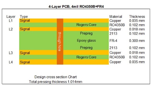
Between the first and second layers, as well as the third and fourth layers, we use the Rogers core, specifically 4mil (0.102mm) RO4350B. This core has a fixed thickness, which plays a crucial role in determining the electrical length of the RF lines on the circuit board. Sandwiched in the middle is the FR - 4 epoxy glass dielectric material. It serves to bond the cores on both the top and bottom sides. The inner layer of the PCB has a copper weight of 0.5 ounces, while the outer layer has a copper weight of 1 ounce.
|
|
|
|
|
Now, let's delve into the detailed specifications of this board:
Base material: RO4350B 0.102mm + Tg 170℃ FR4 0.30mm
Layer count: 4 layers
Panel: 55mm x 132mm = 1 type = 1 piece
Surface finish: Immersion gold
Copper weight: Outer layer 35 um/ Inner layer 18 um
Solder mask / Legend: green / white
Final PCB height: 1.0 mm
Special technology: via in pad (hole filled) under BGA
Standard: IPC 6012 Class 2
Packing: 25 panels are packed for shipment.
Lead time: 12 working days
Shelf life: 6 months |
|
|
|
 |
|
|
|
This 4-layer high-frequency PCB combines 4mil RO4350B and FR-4 materials, offering a simple and cost-effective solution ideal for entering new markets. The RO4350B hybrid PCB is widely used in applications such as preamplifiers, radar sensors, digital transmitters, and splitter modules; GPS antennas, communication relays, analog transmitters, and 4G antennas; as well as RF transmitters, WiFi amplifiers, RFID systems, and attenuators. |
|
|
|
The advantages of RO4350B hybrid PCBs: |
|
|
1. Stable Dielectric Constant:
RO4350B maintains a consistent dielectric constant across a wide frequency range, making it an excellent choice for broadband applications.
2. Enhanced Signal Integrity:
It outperforms stack-ups using only FR4 materials, ensuring superior signal performance.
3. Cost Efficiency:
By combining RO4350B with other materials, it offers a more cost-effective solution compared to all low-loss material stack-ups.
4.Reduced High-Frequency Signal Loss:
It minimizes signal loss at high frequencies, ensuring reliable performance in demanding applications.
5. Expert Manufacturing Support:
Leverage our robust capabilities, from prototyping to mass production, backed by IATF 16949 (2016), ISO14001 (2015), ISO9001 (2015), and UL certifications, guaranteeing top-tier quality for your PCBs. |
|
|
|
|
|
That concludes today’s update. Thank you for your time, and feel free to reach out to us for any RF PCB inquiries—we’re here to assist! |
|
|
|
|
|
Appendix: Our PCB Capability 2022 |
|
|
Parameter |
Value |
Layer Counts |
1-32 |
Substrate Material |
RO4350B, RO4003C, RO4730G3, RO4360G2, RO4533, RO4534, RO4535, RO3003, RO3006, RO3010, RO3035, RO3203, RO3210; RT/Duriod 5880; RT/Duriod 5870, RT/Duriod 6002, RT/Duroid 6010, RT/duroid 6035HTC; TMM3, TMM4, TMM6, TMM10, TMM10i, TMM13i, Kappa 438; TLF-35; RF-35TC, RF-60A, RF-60TC, RF-35A2, RF-45, RF-10, TRF-45; TLX-0, TLX-6, TLX-7, TLX-8; TLX-9, TLY-3, TLY-5; PTFE F4B (DK2.2 DK2.65 DK2.85 DK2.94, DK3.0, DK3.2, DK3.38, DK3.5, DK4.0, DK4.4, DK6.15, DK10.2); AD450, AD600, AD1000, TC350; Nelco N4000, N9350, N9240; FR-4 ( High Tg S1000-2M, TU-872 SLK, TU-768, IT-180A etc.), FR-4 High CTI>600V; Polyimide, PET; Metal Core etc. |
Maximum Size |
Flying test: 900*600mm, Fixture test 460*380mm, No test 1100*600mm |
Board Outline Tolerance |
±0.0059" (0.15mm) |
PCB Thickness |
0.0157" - 0.3937" (0.40mm--10.00mm) |
Thickness Tolerance(T≥0.8mm) |
±8% |
Thickness Tolerance(t<0.8mm) |
±10% |
Insulation Layer Thickness |
0.00295" - 0.1969" (0.075mm--5.00mm) |
Minimum Track |
0.003" (0.075mm) |
Minimum Space |
0.003" (0.075mm) |
Outer Copper Thickness |
35µm--420µm (1oz-12oz) |
Inner Copper Thickness |
17µm--350µm (0.5oz - 10oz) |
Drill Hole(Mechanical) |
0.0059" - 0.25" (0.15mm--6.35mm) |
Finished Hole(Mechanical) |
0.0039"-0.248" (0.10mm--6.30mm) |
DiameterTolerance(Mechanical) |
0.00295" (0.075mm) |
Registration (Mechanical) |
0.00197" (0.05mm) |
Aspect Ratio |
12:1 |
Solder Mask Type |
LPI |
Min Soldermask Bridge |
0.00315" (0.08mm) |
Min Soldermask Clearance |
0.00197" (0.05mm) |
Plug via Diameter |
0.0098" - 0.0236" (0.25mm--0.60mm) |
Impedance Control Tolerance |
±10% |
Surface Finish |
HASL,HASL LF,ENIG,Immersion Tin,Immersion Silver, OSP, Gold Finger, Pure gold plated etc. |
|
|
|
|
|
|
Hot Tags:
Rogers RO4350B Substrate |
Rogers RO4350B for Sale |
4mil RO4350B Thickness |
RO4350B Loss Tangent |
RO4350B Hybrid PCB |
|
|
|
