|

|
|
|
|
|
Impedance PCB and Impedance Match |
|
|
|
|
|
The characteristic impedance of the conductor on the printed circuit board is an important indicator of the circuit design, especially in the PCB design of high frequency circuit. Whether the characteristic impedance of the conductor is consistent and matching with the characteristic impedance required by the device or signal must be taken into consideration. Therefore, these two concepts in reliability design of PCB design must be paid attention. |
|
|
|
|
|
There will be a variety of signal transmission in the conductor of circuit board. To increase the rate of transmission, it must increase its frequency. Due to the factors of the circuit itself such as etching, stack thickness, track width and so on are different, it will cause changes of the impedance value, resulting in its signal distortion. Therefore, the impedance value of conductor on high-speed circuit board should be controlled within a certain range, known as the "impedance control". The factors that affect the impedance of the PCB wiring are mainly the width of the copper track, the thickness of the copper track, the dielectric constant of the dielectric, the thickness of the dielectric, the thickness of the pad, the path of the ground layer, the wires around the wiring, etc. So the impedance of the wiring on the board must be controlled in the design of the PCB to avoid signal reflection and other electromagnetic interference and signal integrity issues as far as possible, to guarantee the stability of the actual use of the PCB board. You can refer to the corresponding empirical formula for the calculation method of micro-strip line and strip line impedance on PCB board. |
|
|
|
|
|
Definition of Characteristic Impedance
At a certain frequency, relative to a reference layer, the resistance of its high-frequency signals or electromagnetic waves in the process of transmission is called the characteristic impedance, which is the vector summation of electrical impedance, inductive reactance, capacitance resistance. |
|
|
|
|
|
The classification of characteristic impedance |
|
|
Common characteristic impedance is divided into: Бе1БЕ Single ended (line) impedance; (2) Differential impedance and (3) coplanar impedance, etc.
Single ended impedance refers to the measured impedance of a single signal line. Differential impedance refers to the impedance measured between the two transmission lines with equivalent width and spacing in differential drive. Coplanar impedance refers to the impedance measured when the signal line is transmitting between its surrounding GND / VCC (the space between the signal line to GND / VCC on both sides is equal). |
|
|
|
|
|
The Determinant Condition Required for Impedance Control
When the signal is transmitted in the PCB conductor, if the length of conductor is close to the 1/7 of the signal wavelength, then the conductor at this time becomes a signal transmission line, the other general signal transmission lines are required to be done with impedance control. Whether it is required to control the impedance in PCB production is based on the customer's requirement, if the customer requires that a certain line width need to be done with impedance control, it is required to control the impedance of the line width in production.Three basic elements of impedance match are the output impedance (the original active parts), the characteristic impedance (signal line), the input impedance (passive parts) (PCB board) |
|
|
|
|
|
|
|
|
|
|
|
Impedance PCB- Impedance match
If there is signal transmission in the circuit board, it is expected to be smoothly transmitted from the sending end to the receiving end under the condition of minimum energy loss, and the receiving end can completely absorbs it without any reflection. To achieve this kind of transmission, the impedance of the circuit must be equal to the internal impedance of the sending end, which is called "impedance match."
So when the signal is transmitted in the PCB, the characteristic impedance of the PCB board must be matched with the electronic impedance of the head and tail components. Once the impedance value exceeds the tolerance, the transmitted signal energy will be reflected, scattered, attenuated or delayed, resulting in incomplete signal and signal distortion.
Impedance match is one of the design elements when designing high-speed PCB circuits. However, the impedance value is absolutely related with wiring mode. For example, whether wiring on the surface layer or inner layer, the distance from the reference power layer or ground layer, the width of wiring, the PCB material, etc. will affect the characteristic impedance of wiring. That is to say, the impedance value can be determined only after wiring layout, while the characteristic impedance produced by different PCB manufacturers is also slightly different. The wiring layout condition of impedance discontinuity cannot be completely considered in general simulation software due to the limitation of the circuit model or the mathematical algorithm used. In this case, only some temninators, such as series resistors, can be reserved on the schematic diagram to mitigate the effect of discontinuous wiring impedance. The method to completely solve the problem is still trying to avoid the occurrence of impedance discontinuities when wiring layout. |
|
|
|
|
|
| |
 |
| |
| |
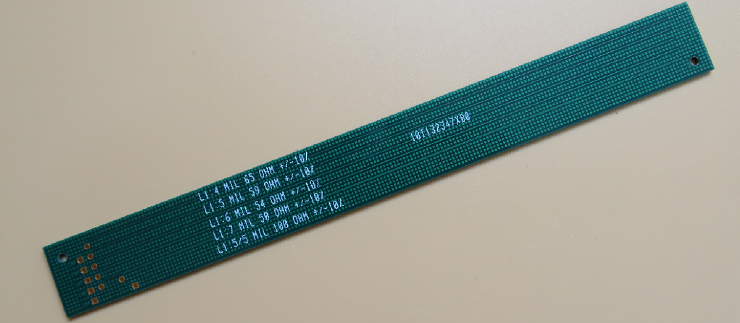
50 ohm Single End Impedance |
|
|
|
|
|
|
|
|
|
|
|
|
|
|
|
|
|
|
|
|
|
|
|