|
|
|
|
F4BTMS High Frequency PCB
|
|
|
|
|
|
Introduction |
|
|
|
|
|
The F4BTMS series is an upgraded version of the F4BTM series. Building upon its foundation, significant technological advancements have been made in material formulation and manufacturing processes. The material now incorporates a large amount of ceramics and utilizes ultra-thin and ultra-fine fiberglass cloth reinforcement. These enhancements have greatly improved the material's performance, resulting in a wider range of dielectric constants. It is a high-reliability material suitable for aerospace applications, capable of replacing similar foreign products. |
|
|
|
|
|
By incorporating a small amount of ultra-thin and ultra-fine fiberglass cloth reinforcement, along with a significant and uniform mixture of special nanoceramics and polytetrafluoroethylene resin, the fiberglass effect during the propagation of electromagnetic waves is minimized, reducing dielectric loss and enhancing dimensional stability. The material exhibits reduced anisotropy in the X/Y/Z directions, allowing for higher frequency usage, increased electrical strength, and improved thermal conductivity. The material also possesses excellent low coefficient of thermal expansion and stable dielectric temperature characteristics. |
|
|
|
|
|
The F4BTMS series comes standard with RTF low roughness copper foil, which not only reduces conductor loss but also provides excellent peel strength. It can be paired with copper-based or aluminum-based options. |
|
|
|
|
|
F4BTMS294 can be combined with buried 50¦¸ resistor copper foil to create a resistor film substrate. |
|
|
|
|
|
The circuit boards can be processed using standard PTFE board fabrication techniques, taking advantage of the excellent mechanical and physical properties of the material. They are suitable for multi-layer, high-layer-count, and backplane processing. Additionally, they exhibit excellent processability in dense hole and fine line routing. |
|
|
|
|
|
Product Features |
|
|
|
|
|
- Minimal dielectric constant tolerance and excellent batch-to-batch consistency. - Extremely low dielectric loss. - Stable dielectric constant and low loss within frequencies up to 40GHz, meeting the requirements of phase-sensitive applications. - Excellent temperature coefficient of dielectric constant and dielectric loss, maintaining frequency and phase stability between -55¡ăC and 150¡ăC. - Excellent resistance to radiation, retaining stable dielectric and physical properties even after exposure to irradiation. - Low outgassing performance, meeting the vacuum outgassing requirements for aerospace applications. - Minimal thermal expansion coefficients in the X/Y/Z directions, ensuring dimensional stability and reliable hole copper connections. - Improved thermal conductivity, suitable for high-power applications. - Excellent dimensional stability. - Low water absorption. |
|
|
|
|
|
Models & Data Sheet |
|
|
|
|
|
here are the technical parameters of the different product models: |
|
|
|
|
|
Product Models: F4BTMS220 F4BTMS233 F4BTMS255 F4BTMS265 F4BTMS294 F4BTMS300 F4BTMS350 F4BTMS430 F4BTMS450 F4BTMS615 F4BTMS1000 |
|
|
|
|
|
Dielectric Constant (Typical): Test Conditions: 10 GHz Values: F4BTMS220: 2.2 F4BTMS233: 2.33 F4BTMS255: 2.55 F4BTMS265: 2.65 F4BTMS294: 2.94 F4BTMS300: 3.00 F4BTMS350: 3.50 F4BTMS430: 4.30 F4BTMS450: 4.50 F4BTMS615: 6.15 F4BTMS1000: 10.20 |
|
|
|
|
|
Dielectric Constant Tolerance: Values: F4BTMS220: +/-0.02; F4BTMS233: +/-0.03; F4BTMS255: +/-0.04; F4BTMS265: +/-0.04; F4BTMS294: +/-0.04; F4BTMS300: +/-0.04; F4BTMS350: +/-0.04; F4BTMS430: +/-0.05; F4BTMS450: +/-0.09; F4BTMS615: +/-0.09; F4BTMS1000: +/-0.12 |
|
|
|
|
|
Dielectric Constant (Design): Test Conditions: 10 GHz Values are the same as the "Dielectric Constant (Typical)" section. |
|
|
|
|
|
Loss Tangent (Typical): Test Conditions: 10 GHz 20 GHz 40 GHz |
|
|
|
|
|
Values: F4BTMS220: 10 GHz: 0.0009 20 GHz: 0.0010 40 GHz: 0.0013 |
|
|
|
|
|
F4BTMS233: 10 GHz: 0.0010 20 GHz: 0.0011 40 GHz: 0.0015 |
|
|
|
|
|
F4BTMS255: 10 GHz: 0.0012 20 GHz: 0.0013 40 GHz: 0.0016 |
|
|
|
|
|
F4BTMS265: 10 GHz: 0.0012 20 GHz: 0.0014 40 GHz: 0.0018 |
|
|
|
|
|
F4BTMS294: 10 GHz: 0.0012 20 GHz: 0.0014 40 GHz: 0.0018 |
|
|
|
|
|
F4BTMS300: 10 GHz: 0.0013 20 GHz: 0.0015 40 GHz: 0.0019 |
|
|
|
|
|
F4BTMS350: 10 GHz: 0.0016 20 GHz: 0.0019 40 GHz: 0.0024 |
|
|
|
|
|
F4BTMS350: 10 GHz: 0.0016 20 GHz: 0.0019 40 GHz: 0.0024 |
|
|
|
|
|
F4BTMS450: 10 GHz: 0.0015 20 GHz: 0.0019 40 GHz: 0.0024 |
|
|
|
|
|
F4BTMS615: 10 GHz: 0.0020 20 GHz: 0.0023 40 GHz: / |
|
|
|
|
|
F4BTMS1000: 10 GHz: 0.0020 20 GHz: 0.0023 40 GHz: / |
|
|
|
|
|
| |
Product Technical Parameters |
Product Models & Data Sheet |
Product Features |
Test Conditions |
Unit |
F4BTMS220 |
F4BTMS233 |
F4BTMS255 |
F4BTMS265 |
F4BTMS294 |
F4BTMS300 |
F4BTMS350 |
F4BTMS430 |
F4BTMS450 |
F4BTMS615 |
F4BTMS1000 |
Dielectric Constant (Typical) |
10GHz |
/ |
2.2 |
2.33 |
2.55 |
2.65 |
2.94 |
3.00 |
3.50 |
4.30 |
4.50 |
6.15 |
10.20 |
Dielectric Constant Tolerance |
/ |
/ |
±0.02 |
±0.03 |
±0.04 |
±0.04 |
±0.04 |
±0.04 |
±0.05 |
±0.09 |
±0.09 |
±0.12 |
±0.2 |
Dielectric Constant (Design) |
10GHz |
/ |
2.2 |
2.33 |
2.55 |
2.65 |
2.94 |
3.0 |
3.50 |
4.3 |
4.5 |
6.15 |
10.2 |
Loss Tangent (Typical) |
10GHz |
/ |
0.0009 |
0.0010 |
0.0012 |
0.0012 |
0.0012 |
0.0013 |
0.0016 |
0.0015 |
0.0015 |
0.0020 |
0.0020 |
20GHz |
/ |
0.0010 |
0.0011 |
0.0013 |
0.0014 |
0.0014 |
0.0015 |
0.0019 |
0.0019 |
0.0019 |
0.0023 |
0.0023 |
40GHz |
/ |
0.0013 |
0.0015 |
0.0016 |
0.0018 |
0.0018 |
0.0019 |
0.0024 |
0.0024 |
0.0024 |
/ |
/ |
Dielectric Constant Temperature Coefficient |
-55 º~150ºC |
PPM/¡æ |
-130 |
-122 |
-92 |
-88 |
-20 |
-20 |
-39 |
-60 |
-58 |
-96 |
-320 |
Peel Strength |
1 OZ RTF copper |
N/mm |
>2.4 |
>2.4 |
>1.8 |
>1.8 |
>1.2 |
>1.2 |
>1.2 |
>1.2 |
>1.2 |
>1.2 |
>1.2 |
Volume Resistivity |
Standard Condition |
MΩ.cm |
¡Ư1¡Á10^8 |
¡Ư1¡Á10^8 |
¡Ư1¡Á10^8 |
¡Ư1¡Á10^8 |
¡Ư1¡Á10^8 |
¡Ư1¡Á10^8 |
¡Ư1¡Á10^8 |
¡Ư1¡Á10^8 |
¡Ư1¡Á10^8 |
¡Ư1¡Á10^8 |
¡Ư1¡Á10^8 |
|
| |
Surface Resistivity |
Standard Condition |
MΩ |
¡Ư1¡Á10^8 |
¡Ư1¡Á10^8 |
¡Ư1¡Á10^8 |
¡Ư1¡Á10^8 |
¡Ư1¡Á10^8 |
¡Ư1¡Á10^8 |
¡Ư1¡Á10^8 |
¡Ư1¡Á10^8 |
¡Ư1¡Á10^8 |
¡Ư1¡Á10^8 |
¡Ư1¡Á10^8 |
Electrical Strength (Z direction) |
5KW, 500V/s |
KV/mm |
>26 |
>30 |
>32 |
>34 |
>40 |
>40 |
>42 |
>44 |
>45 |
>48 |
>23 |
Breakdown Voltage (XY direction) |
5KW, 500V/s |
KV |
>35 |
>38 |
>40 |
>42 |
>48 |
>52 |
>55 |
>52 |
>54 |
>55 |
>42 |
Coefficientof Thermal Expansion (X, Y direction) |
-55 º~288ºC |
ppm/ºC |
40, 50 |
35, 40 |
15, 20 |
15, 20 |
10, 12 |
10, 11 |
10, 12 |
13, 12 |
12, 12 |
10, 12 |
16, 18 |
Coefficientof Thermal Expansion (Z direction) |
-55 º~288ºC |
ppm/ºC |
290 |
220 |
80 |
72 |
22 |
22 |
20 |
47 |
45 |
40 |
32 |
Thermal Stress |
260¡æ, 10s, 3 times |
/ |
No delamination |
No delamination |
No delamination |
No delamination |
No delamination |
No delamination |
No delamination |
No delamination |
No delamination |
No delamination |
No delamination |
Water Absorption |
20±2¡æ, 24 hours |
% |
0.02 |
0.02 |
0.025 |
0.025 |
0.02 |
0.025 |
0.03 |
0.08 |
0.08 |
0.1 |
0.03 |
Density |
Room Temperature |
g/cm3 |
2.18 |
2.22 |
2.26 |
2.26 |
2.25 |
2.28 |
2.3 |
2.51 |
2.53 |
2.75 |
3.2 |
Long-Term Operating Temperature |
High-Low Temperature Chamber |
¡æ |
-55¡«+260 |
-55¡«+260 |
-55¡«+260 |
-55¡«+260 |
-55¡«+260 |
-55¡«+260 |
-55¡«+260 |
-55¡«+260 |
-55¡«+260 |
-55¡«+260 |
-55¡«+260 |
Thermal Conductivity |
Z direction |
W/(M.K) |
0.26 |
0.28 |
0.31 |
0.36 |
0.58 |
0.58 |
0.6 |
0.63 |
0.64 |
0.67 |
0.81 |
Flammability |
/ |
UL-94 |
V-0 |
V-0 |
V-0 |
V-0 |
V-0 |
V-0 |
V-0 |
V-0 |
V-0 |
V-0 |
V-0 |
Material Composition |
/ |
/ |
PTFE, Ultra-thin and ultra-fine (quartz) fiberglass. |
PTFE, Ultra-thin and ultra-fine fiberglass, ceramics. |
|
|
|
|
|
|
|
Our PCB Capability (F4BTMS) |
|
|
|
|
|
Here's the details of the capabilities: |
|
|
|
|
|
Layer count: Our PCBs are available in Single Sided, Double Sided PCB, Multilayer PCB, and Hybrid PCB configurations, providing flexibility to meet various design requirements. |
|
|
|
|
|
Copper weight: We offer different copper weight options including 0.5oz (17 ¦̀m), 1oz (35¦̀m), and 2oz (70¦̀m), allowing you to choose the appropriate copper thickness for your specific application. |
|
|
|
|
|
Dielectric thickness: Our PCBs support a wide range of dielectric thicknesses to accommodate diverse design needs. You can select from options such as 0.09mm (3.5mil), 0.127mm (5mil), 0.254mm (10mil), 0.508mm (20mil), 0.635mm (25mil), 0.762mm (30mil), 0.787mm (31mil), 1.016mm (40mil), 1.27mm (50mil), 1.5mm (59mil), 1.524mm (60mil), 1.575mm (62mil), 2.03mm (80mil), 2.54mm (100mil), 3.175mm (125mil), 4.6mm (160mil), 5.08mm (200mil), and 6.35mm (250mil). |
|
|
|
|
|
PCB size: Our capabilities support PCB sizes up to 400mm X 500mm, providing ample space for your PCB designs. |
|
|
|
|
|
Solder mask: We offer a variety of solder mask colors including Green, Black, Blue, Yellow, Red, and more. You can choose the solder mask color that suits your aesthetic preferences or specific requirements. |
|
|
|
|
|
Surface finish: We provide a range of surface finish options to protect and enhance the functionality of your PCB. Surface finish options include Bare copper, HASL (Hot Air Solder Leveling), ENIG (Electroless Nickel Immersion Gold), Immersion silver, Immersion tin, OSP (Organic Solderability Preservative), Pure gold, ENEPIG (Electroless Nickel Electroless Palladium Immersion Gold), and more. These finishes offer different advantages such as improved solderability, corrosion resistance, and wire bonding capabilities. |
|
|
|
|
|
| |
PCB Capability (F4BTMS) |
PCB Material: |
PTFE£¬Ultra-thin and ultra-fine fiberglass, ceramics. |
Designation (F4BTMS ) |
F4BTMS |
DK (10GHz) |
DF (10 GHz) |
F4BTMS220 |
2.2±0.02 |
0.0009 |
F4BTMS233 |
2.33±0.03 |
0.0010 |
F4BTMS255 |
2.55±0.04 |
0.0012 |
F4BTMS265 |
2.65±0.04 |
0.0012 |
F4BTMS294 |
2.94±0.04 |
0.0012 |
F4BTMS300 |
3.0±0.04 |
0.0013 |
F4BTMS350 |
3.5±0.05 |
0.0016 |
F4BTMS430 |
4.3±0.09 |
0.0015 |
F4BTMS450 |
4.5±0.09 |
0.0015 |
F4BTMS615 |
6.15±0.12 |
0.0020 |
F4BTMS1000 |
10.2±0.2 |
0.0020 |
Layer count: |
Single Sided, Double Sided PCB, Multilayer PCB, Hybrid PCB |
Copper weight: |
0.5oz (17 µm), 1oz (35µm), 2oz (70µm) |
Dielectric thickness |
0.09mm (3.5mil), 0.127mm (5mil), 0.254mm(10mil),0.508mm(20mil), 0.635mm(25mil), 0.762mm(30mil), 0.787mm(31mil), 1.016mm(40mil), 1.27mm(50mil), 1.5mm(59mil), 1.524mm(60mil), 1.575mm(62mil), 2.03mm(80mil), 2.54mm(100mil), 3.175mm(125mil), 4.6mm(160mil), 5.08mm(200mil), 6.35mm(250mil) |
PCB size: |
¡Ü400mm X 500mm |
Solder mask: |
Green, Black, Blue, Yellow, Red etc. |
Surface finish: |
Bare copper, HASL, ENIG, Immersion silver, Immersion tin, OSP, Pure gold, ENEPIG etc.. |
|
|
|
|
|
|
|
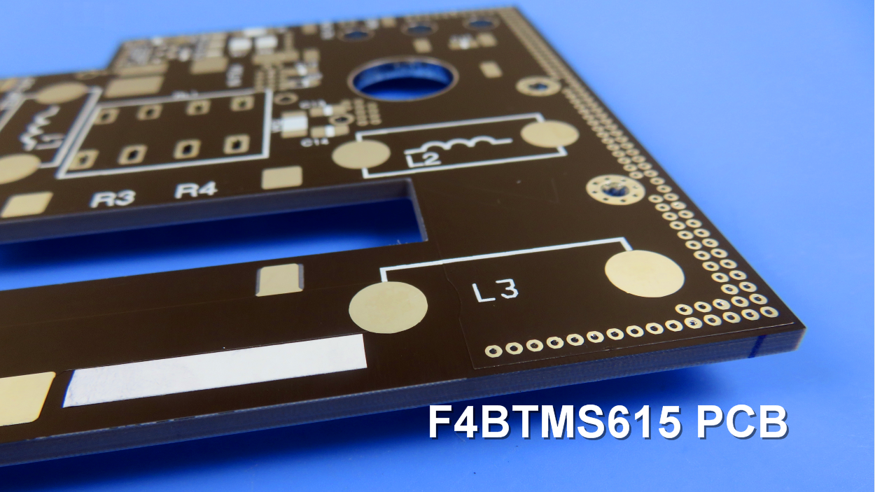
A F4BTMS PCB and Typical Applications: |
|
|
|
|
|
Presented on the screen is an F4BTMS high-frequency PCB, utilizing a 3.2mm substrate with HASL coating on the pads. F4BTMS PCBs are extensively employed in various domains, including: |
|
|
|
|
|
Aerospace and aviation equipment, space installations, and cabin setups. Microwave and RF applications. Radar systems, particularly in military applications. Feed networks for signal distribution. Phase-sensitive antennas and phased array antennas. Satellite communications, and much more. |
|
|
|
|
|
|
|
|
|
|
|
Final (F4BTMS series aluminum-based/copper-based boards) This series of laminates can provide aluminum-based or copper-based materials, where one side of the dielectric layer is covered with copper foil, and the other side is covered with an aluminum-based or copper-based layer. This configuration serves as shielding or heat dissipation. |
|
|
|
|
|
The model numbers are F4BTMS***-AL or F4BTMS***-CU. For example, F4BTMS220-AL represents F4BTMS220 with aluminum-based substrate. F4BTMS294-CU represents F4BTMS294 with copper-based substrate. |
|
|
|
|
|
|
|
|
|
|