|
|
|
|
|
|
|
|
|
|
Introduction |
|
|
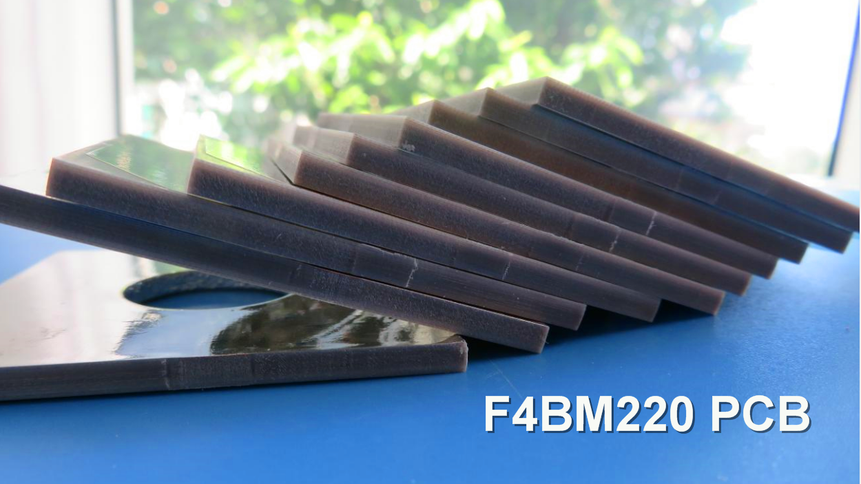
These series laminates are made by scientifically formulating and strictly pressing a combination of fiberglass cloth, polytetrafluoroethylene resin, and polytetrafluoroethylene film. Its electrical performance is improved compared to F4B, mainly due to a wider range of dielectric constants, lower dielectric loss, increased insulation resistance, and improved stability. It can replace similar foreign products. |
|
|
|
|
|
F4BM and F4BME have the same dielectric layer but different copper foil combinations: F4BM is paired with ED copper foil, suitable for applications without PIM requirements; F4BME is paired with reverse-treated foil (RTF) copper foil, offering excellent PIM performance, more precise line control, and lower conductor loss. |
|
|
|
|
|
By adjusting the ratio between polytetrafluoroethylene and fiberglass cloth, F4BM and F4BME achieve precise control of the dielectric constant, providing low loss and enhanced dimensional stability. A higher dielectric constant corresponds to a higher proportion of fiberglass, resulting in better dimensional stability, lower thermal expansion coefficient, improved temperature drift, and a slight increase in dielectric loss. |
|
|
|
|
|
Features & Benefits |
|
|
-DK options available: 2.17 to 3.0, customizable DK
-Low loss
-F4BME paired with RTF copper foil, excellent PIM performance
-Diverse sizes, cost-effective
-Radiation resistance, low outgassing
-Commercialized, large-scale production, high cost-effectiveness |
|
|
|
|
|
Laminate Models and Data Sheet |
|
|
Here's a detailed description of each section of the data sheet: |
|
|
|
|
|
Product Model & Data Sheet:
This section simply identifies the data sheet as the documentation for a range of product models. The models listed are F4BM217, F4BM220, F4BM233, F4BM245, F4BM255, F4BM265, F4BM275, F4BM294, and F4BM300. |
|
|
|
|
|
Product Features:
This section provides an overview of the features of the products and introduces the technical parameters that will be described in the subsequent sections. |
|
|
|
|
|
Technical Parameters: |
|
|
|
|
|
Dielectric Constant (Typical):
This parameter measures the relative permittivity of the material at a frequency of 10GHz. The data sheet lists the typical dielectric constant values for each product model. For example, F4BM217 has a dielectric constant of 2.17, while F4BM300 has a dielectric constant of 3.0. |
|
|
|
|
|
Dielectric Constant Tolerance:
This parameter specifies the tolerance range for the dielectric constant values. The values listed indicate the allowable deviation from the typical dielectric constant values. The tolerance range is the same for all models. |
|
|
|
|
|
Loss Tangent (Typical):
Loss tangent measures the dissipation of electromagnetic energy in the material. The data sheet provides loss tangent values at two different frequencies: 10GHz and 20GHz. Each model has specific loss tangent values associated with these frequencies. |
|
|
|
|
|
Dielectric Constant Temperature Coefficient:
This parameter describes how the dielectric constant of the material changes with temperature. The data sheet provides temperature coefficient values in parts per million per degree Celsius (PPM/¡æ) over a temperature range of -55ºC to 150ºC. Each model has a different temperature coefficient value. |
|
|
|
|
|
Peel Strength:
Peel strength refers to the adhesive strength between the material and a specified substrate. The data sheet lists peel strength values for two different conditions: 1 OZ F4BM and 1 OZ F4BME. The values indicate the minimum required peel strength for each model. |
|
|
|
|
|
Volume Resistivity:
Volume resistivity measures the electrical resistance within the material. The data sheet provides minimum volume resistivity values under standard conditions. The unit of measurement is megaohm-centimeters (MΩ.cm), and all models have the same minimum value. |
|
|
|
|
|
Surface Resistivity:
Surface resistivity measures the electrical resistance across the surface of the material. The data sheet provides minimum surface resistivity values under standard conditions. The unit of measurement is megaohms (MΩ), and all models have the same minimum value. |
|
|
|
|
|
Electrical Strength (Z direction):
Electrical strength refers to the ability of the material to withstand electrical stress in the Z direction (perpendicular to the surface). The data sheet provides the minimum electrical strength values in kilovolts per millimeter (KV/mm) for each model. |
|
|
|
|
|
Breakdown Voltage (XY direction):
Breakdown voltage is the voltage at which electrical breakdown occurs in the XY direction (parallel to the surface). The data sheet provides the minimum breakdown voltage values in kilovolts (KV) for each model. |
|
|
|
|
|
Coefficient of Thermal Expansion:
This parameter describes how the material expands or contracts with changes in temperature. The data sheet provides coefficient of thermal expansion values in parts per million per degree Celsius (ppm/ºC) for both the XY direction and the Z direction. The values are given over a temperature range of -55ºC to 288ºC. |
|
|
|
|
|
Thermal Stress:
Thermal stress is assessed by subjecting the material to specific temperature conditions. The data sheet indicates that the material does not experience delamination (separation of layers) when exposed to a temperature of 260¡æ for 10 seconds, repeated three times. |
|
|
|
|
|
Water Absorption:
Water absorption measures the amount of water the material can absorb under specific conditions. The data sheet lists the maximum water absorption values as a percentage of the material's weight. The measurements are taken at a temperature of 20±2¡æ for 24 hours. |
|
|
|
|
|
Density:
Density refers to the mass per unit volume of the material. The data sheet provides the density values at room temperature in grams per cubic centimeter (g/cm3) for each model. |
|
|
|
|
|
Long-Term Operating Temperature:
This parameter specifies the recommended temperature range for long-term operation of the material. The data sheet indicates that all models can operate within a temperature range of -55 to +260¡æ. |
|
|
|
|
|
Thermal Conductivity:
Thermal conductivity measures the material's ability to conduct heat. The data sheet provides the thermal conductivity values in the Z direction (perpendicular to the surface) in watts per meter-kelvin (W/(M.K)) for each model. |
|
|
|
|
|
PIM (Passive Intermodulation):
Passive Intermodulation (PIM) is a measure of unwanted signal distortion. The data sheet states that PIM measurements are onlyapplicable to the F4BME model. Unfortunately, the specific values or units for PIM are not provided in the information you provided. |
|
|
|
|
|
Flammability:
Flammability indicates the material's resistance to catching fire. The data sheet states that the material has a flammability rating of V-0 according to the UL-94 standard. The V-0 rating signifies the highest level of flame resistance. |
|
|
|
|
|
Material Composition:
This section provides information about the composition of the material used in the products. It mentions that the material is composed of PTFE (polytetrafluoroethylene), fiberglass cloth, and copper foil. |
|
|
|
|
|
| |
Product Technical Parameters |
Product Model & Data Sheet |
|
Product Features |
Test Conditions |
Unit |
F4BM217 |
F4BM220 |
F4BM233 |
F4BM245 |
|
Dielectric Constant (Typical) |
10GHz |
/ |
2.17 |
2.2 |
2.33 |
2.45 |
|
Dielectric Constant Tolerance |
/ |
/ |
±0.04 |
±0.04 |
±0.04 |
±0.05 |
|
Loss Tangent (Typical) |
10GHz |
/ |
0.001 |
0.001 |
0.0011 |
0.0012 |
|
20GHz |
/ |
0.0014 |
0.0014 |
0.0015 |
0.0017 |
|
Dielectric Constant Temperature Coefficient |
-55ºC¡«150ºC |
PPM/¡æ |
-150 |
-142 |
-130 |
-120 |
|
Peel Strength |
1 OZ F4BM |
N/mm |
>1.8 |
>1.8 |
>1.8 |
>1.8 |
|
1 OZ F4BME |
N/mm |
>1.6 |
>1.6 |
>1.6 |
>1.6 |
|
Volume Resistivity |
Standard Condition |
MΩ.cm |
¡Ư6¡Á10^6 |
¡Ư6¡Á10^6 |
¡Ư6¡Á10^6 |
¡Ư6¡Á10^6 |
|
Surface Resistivity |
Standard Condition |
MΩ |
¡Ư1¡Á10^6 |
¡Ư1¡Á10^6 |
¡Ư1¡Á10^6 |
¡Ư1¡Á10^6 |
|
Electrical Strength (Z direction) |
5KW£¬500V/s |
KV/mm |
>23 |
>23 |
>23 |
>25 |
|
Breakdown Voltage (XY direction) |
5KW£¬500V/s |
KV |
>30 |
>30 |
>32 |
>32 |
|
Coefficientof Thermal Expansion |
XY direction |
-55 º~288ºC |
ppm/ºC |
25, 34 |
25, 34 |
22, 30 |
20, 25 |
|
Z direction |
-55 º~288ºC |
ppm/ºC |
240 |
240 |
205 |
187 |
|
Thermal Stress |
260¡æ, 10s£¬3 times |
No delamination |
No delamination |
No delamination |
No delamination |
|
Water Absorption |
20±2¡æ, 24 hours |
% |
¡Ü0.08 |
¡Ü0.08 |
¡Ü0.08 |
¡Ü0.08 |
|
Density |
Room Temperature |
g/cm3 |
2.17 |
2.18 |
2.20 |
2.22 |
|
Long-Term Operating Temperature |
High-Low Temperature Chamber |
¡æ |
-55¡«+260 |
-55¡«+260 |
-55¡«+260 |
-55¡«+260 |
|
Thermal Conductivity |
Z direction |
W/(M.K) |
0.24 |
0.24 |
0.28 |
0.30 |
|
PIM |
Only applicable to F4BME |
dBc |
¡Ü-159 |
¡Ü-159 |
¡Ü-159 |
¡Ü-159 |
|
Flammability |
/ |
UL-94 |
V-0 |
V-0 |
V-0 |
V-0 |
|
Material Composition |
/ |
/ |
PTFE, Fiberglass Cloth
F4BM paired with ED copper foil, F4BME paired with reverse-treated (RTF) copper foil. |
|
|
| |
Product Technical Parameters |
Product Model & Data Sheet |
Product Features |
Test Conditions |
Unit |
F4BM255 |
F4BM265 |
F4BM275 |
F4BM294 |
F4BM300 |
Dielectric Constant (Typical) |
10GHz |
/ |
2.55 |
2.65 |
2.75 |
2.94 |
3.0 |
Dielectric Constant Tolerance |
/ |
/ |
±0.05 |
±0.05 |
±0.05 |
±0.06 |
±0.06 |
Loss Tangent (Typical) |
10GHz |
/ |
0.0013 |
0.0013 |
0.0015 |
0.0016 |
0.0017 |
|
20GHz |
/ |
0.0018 |
0.0019 |
0.0021 |
0.0023 |
0.0025 |
Dielectric Constant Temperature Coefficient |
-55ºC¡«150ºC |
PPM/¡æ |
-110 |
-100 |
-92 |
-85 |
-80 |
Peel Strength |
1 OZ F4BM |
N/mm |
>1.8 |
>1.8 |
>1.8 |
>1.8 |
>1.8 |
|
1 OZ F4BME |
N/mm |
>1.6 |
>1.6 |
>1.6 |
>1.6 |
>1.6 |
Volume Resistivity |
Standard Condition |
MΩ.cm |
¡Ư6¡Á10^6 |
¡Ư6¡Á10^6 |
¡Ư6¡Á10^6 |
¡Ư6¡Á10^6 |
¡Ư6¡Á10^6 |
Surface Resistivity |
Standard Condition |
MΩ |
¡Ư1¡Á10^6 |
¡Ư1¡Á10^6 |
¡Ư1¡Á10^6 |
¡Ư1¡Á10^6 |
¡Ư1¡Á10^6 |
Electrical Strength (Z direction) |
5KW£¬500V/s |
KV/mm |
>25 |
>25 |
>28 |
>30 |
>30 |
Breakdown Voltage (XY direction) |
5KW£¬500V/s |
KV |
>34 |
>34 |
>35 |
>36 |
>36 |
Coefficientof Thermal Expansion |
XY direction |
-55 º~288ºC |
ppm/ºC |
16, 21 |
14, 17 |
14, 16 |
12, 15 |
12, 15 |
|
Z direction |
-55 º~288ºC |
ppm/ºC |
173 |
142 |
112 |
98 |
95 |
Thermal Stress |
260¡æ, 10s£¬3 times |
No delamination |
No delamination |
No delamination |
No delamination |
No delamination |
Water Absorption |
20±2¡æ, 24 hours |
% |
¡Ü0.08 |
¡Ü0.08 |
¡Ü0.08 |
¡Ü0.08 |
¡Ü0.08 |
Density |
Room Temperature |
g/cm3 |
2.25 |
2.25 |
2.28 |
2.29 |
2.29 |
Long-Term Operating Temperature |
High-Low Temperature Chamber |
¡æ |
-55¡«+260 |
-55¡«+260 |
-55¡«+260 |
-55¡«+260 |
-55¡«+260 |
Thermal Conductivity |
Z direction |
W/(M.K) |
0.33 |
0.36 |
0.38 |
0.41 |
0.42 |
PIM |
Only applicable to F4BME |
dBc |
¡Ü-159 |
¡Ü-159 |
¡Ü-159 |
¡Ü-159 |
¡Ü-159 |
Flammability |
/ |
UL-94 |
V-0 |
V-0 |
V-0 |
V-0 |
V-0 |
Material Composition |
/ |
/ |
PTFE, Fiberglass Cloth
F4BM paired with ED copper foil, F4BME paired with reverse-treated (RTF) copper foil. |
|
|
|
|
|
|
|
Our PCB Capability (F4BM ) |
|
|
Our PCB capability includes the following options: |
|
|
|
|
|
Layer count:
We offer Single Sided, Double Sided PCBs, as well as Multilayer PCBs and Hybrid PCBs. |
|
|
|
|
|
Copper weight:
You can select from three options for copper weight: 0.5oz (17 µm), 1oz (35µm), and 2oz (70µm). |
|
|
|
|
|
Dielectric thickness (or overall thickness):
We provide a range of dielectric thickness options:
0.127mm (dielectric)
0.2mm, 0.25mm, 0.5mm, 0.508mm, 0.762mm
0.8mm, 1.0mm, 1.5mm, 1.524mm, 1.575mm
2.0mm, 2.5mm, 3.0mm, 4.0mm, 5.0mm, 6.0mm, 8.0mm, 10.0mm, 12.0mm
PCB size:
The maximum size we support is ¡Ü400mm X 500mm. |
|
|
|
|
|
Solder mask:
You have the option to choose from various solder mask colors, including Green, Black, Blue, Yellow, Red, and more. |
|
|
|
|
|
Surface finish:
We offer a range of surface finish options for your PCB:
Bare copper
HASL (Hot Air Solder Leveling)
ENIG (Electroless Nickel Immersion Gold)
Immersion silver
Immersion tin
OSP (Organic Solderability Preservative)
Pure gold
ENEPIG (Electroless Nickel Electroless Palladium Immersion Gold) |
|
|
|
|
|
These capabilities provide you with flexibility in designing and manufacturing your PCBs. If you have any specific requirements or further questions, please let us know. We are here to assist you! |
|
|
|
|
|
| |
PCB Material: |
PTFE glass fiber cloth copper clad laminates |
Designation (F4BM ) |
F4BM |
DK (10GHz) |
DF (10 GHz) |
F4BM217 |
2.17±0.04 |
0.0010 |
F4BM220 |
2.20±0.04 |
0.0010 |
F4BM233 |
2.33±0.04 |
0.0011 |
F4BM245 |
2.45±0.05 |
0.0012 |
F4BM255 |
2.55±0.05 |
0.0013 |
F4BM265 |
2.65±0.05 |
0.0013 |
F4BM275 |
2.75±0.05 |
0.0015 |
F4BM294 |
2.94±0.06 |
0.0016 |
F4BM300 |
3.00±0.06 |
0.0017 |
Layer count: |
Single Sided, Double Sided PCB, Multilayer PCB, Hybrid PCB |
Copper weight: |
0.5oz (17 µm), 1oz (35µm), 2oz (70µm) |
Dielectric thickness (or overall thickness) |
0.127mm (dielectric), 0.2mm, 0.25mm, 0.5mm, 0.508mm, 0.762mm, 0.8mm, 1.0mm, 1.5mm, 1.524mm, 1.575mm, 2.0mm, 2.5mm, 3.0mm, 4.0mm, 5.0mm, 6.0mm, 8.0mm, 10.0mm, 12.0mm |
PCB size: |
¡Ü400mm X 500mm |
Solder mask: |
Green, Black, Blue, Yellow, Red etc. |
Surface finish: |
Bare copper, HASL, ENIG, Immersion silver, Immersion tin, OSP, Pure gold, ENEPIG etc.. |
|
|
|
|
|
|
|
A PCB and Typical Applications |
|
|
Displayed on the screen is a 2-layer copper high-frequency PCB with a low DK of 2.2, utilizing F4BM material and HASL surface finish on a 3.0mm substrate. |
|
|
|
|
|
F4BM high-frequency PCB finds applications in microwave, RF, and radar systems, as well as in phase shifters, passive components, power dividers, couplers, combiners, feed networks, phased array antennas, satellite communications, and base station antennas. |
|
|
|
|
|
|
|
|
|
|
|
Final - F4BM series aluminum-based/copper-based boards
These F4BM series of laminates can provide aluminum-based or copper-based materials, where one side of the dielectric layer is covered with copper foil, and the other side is covered with either aluminum-based material or copper-based , serving as shielding or heat dissipation purposes. |
|
|
|
|
|
Model examples
F4BM220-AL represents F4BM220 with an aluminum-based substrate. |
|
|
|
|
|
|
|
|
|
|