|
|
|
|
|
|
|
|
|
|
Introduction |
|
|
These series laminates are made by scientifically formulating and strictly pressing a combination of fiberglass cloth, polytetrafluoroethylene resin, and polytetrafluoroethylene film. Its electrical performance is improved compared to F4B, mainly due to a wider range of dielectric constants, lower dielectric loss, increased insulation resistance, and improved stability. It can replace similar foreign products. |
|
|
|
|
|
F4BME and F4BM have the same dielectric layer but different copper foil combinations: F4BME is paired with reverse-treated foil (RTF) copper foil, offering excellent PIM performance, more precise line control, and lower conductor loss. F4BM is paired with ED copper foil, suitable for applications without PIM requirements. |
|
|
|
|
|
By adjusting the ratio between polytetrafluoroethylene and fiberglass cloth, F4BM and F4BME achieve precise control of the dielectric constant, providing low loss and enhanced dimensional stability. A higher dielectric constant corresponds to a higher proportion of fiberglass, resulting in better dimensional stability, lower thermal expansion coefficient, improved temperature drift, and a slight increase in dielectric loss. |
|
|
|
|
|
Features & Benefits |
|
|
-DK options available: 2.17 to 3.0, customizable DK
-Low loss
-F4BME paired with RTF copper foil, excellent PIM performance
-Diverse sizes, cost-effective
-Radiation resistance, low outgassing
-Commercialized, large-scale production, high cost-effectiveness |
|
|
|
|
|
Laminate Models and Data Sheet |
|
|
The data sheet provides technical parameters and specifications for a specific product model. It includes various characteristics and performance measurements of the product. This information is essential for potential customers, engineers, and other stakeholders who need to understand the capabilities and limitations of the product. |
|
|
|
|
|
Let's go through the product's technical parameters as mentioned in the data sheet: |
|
|
|
|
|
Dielectric Constant (Typical):
Test Conditions: Measured at 10GHz.
The dielectric constant values are provided for different product models ranging from F4BME217 to F4BME300. |
|
|
|
|
|
Dielectric Constant Tolerance:
The dielectric constant tolerance values indicate the acceptable deviation from the typical dielectric constant for each product model. |
|
|
|
|
|
Loss Tangent (Typical):
Test Conditions: Measured at 10GHz and 20GHz.
The loss tangent values represent the dissipation of energy within the material at different frequencies for each product model. |
|
|
|
|
|
Dielectric Constant Temperature Coefficient:
Test Conditions: Measured over a temperature range from -55ºC to 150ºC.
Unit: PPM/¡æ (parts per million per degree Celsius).
The temperature coefficient values indicate how the dielectric constant changes with temperature for each product model. |
|
|
|
|
|
Peel Strength:
Unit: N/mm (Newton per millimeter).
The peel strength values represent the bonding strength between different layers of the material for each product model. |
|
|
|
|
|
Volume Resistivity:
Test Conditions: Standard conditions.
Unit: MΩ.cm (megaohm centimeters).
The volume resistivity values indicate the resistance to electric current flow through the material for each product model. |
|
|
|
|
|
Surface Resistivity:
Test Conditions: Standard conditions.
Unit: MΩ (megaohms).
The surface resistivity values indicate the resistance to electric current flow across the surface of the material for each product model. |
|
|
|
|
|
Electrical Strength (Z direction):
Test Conditions: Measured at 5KW with a voltage change rate of 500V/s.
Unit: KV/mm (kilovolts per millimeter).
The electrical strength values represent the ability of the material to withstand electric stress in the Z direction for each product model. |
|
|
|
|
|
Breakdown Voltage (XY direction):
Test Conditions: Measured at 5KW with a voltage change rate of 500V/s.
Unit: KV (kilovolts).
The breakdown voltage values indicate the voltage at which the material fails in the XY direction for each product model. |
|
|
|
|
|
Coefficient of Thermal Expansion:
Test Conditions: Measured over a temperature range from -55ºC to 288ºC.
Unit: ppm/ºC (parts per million per degree Celsius).
The coefficient of thermal expansion values represent the material's dimensional change with temperature in both the XY direction and the Z direction. |
|
|
|
|
|
Thermal Stress:
Test Conditions: Measured at 260¡æ for 10 seconds, repeated three times.
The thermal stress values indicate whether the material experiences delamination under high-temperature conditions for each product model. |
|
|
|
|
|
Water Absorption:
Test Conditions: Measured at 20±2¡æ for 24 hours.
Unit: Percentage (%).
The water absorption values indicate the material's ability to absorb water under specific conditions for each product model. |
|
|
|
|
|
Density:
Test Conditions: Measured at room temperature.
Unit: g/cm3 (grams per cubic centimeter).
The density values represent the mass per unit volume of the material for each product model. |
|
|
|
|
|
Long-Term Operating Temperature:
Test Conditions: Measured in a high-low temperature chamber.
Unit: ¡æ (degrees Celsius).
The long-term operating temperature values indicate the recommended temperature range for continuous operation of the material for each product model. |
|
|
|
|
|
Thermal Conductivity (Z direction):
Test Conditions: Not specified.
Unit: W/(M.K) (watts per meter Kelvin).
The thermal conductivity values represent the material's ability to conduct heat in the Z direction for each product model. |
|
|
|
|
|
PIM (Passive Intermodulation):
Test Conditions: Only applicable to F4BME product model.
Unit: dBc (decibels relative to the carrier).
The PIM value represents the level of passive intermodulation distortion for the specific product model. |
|
|
|
|
|
Flammability:
The flammability values indicate the product's resistance to burning and its compliance with the UL-94 standard. V-0 is the highest rating. |
|
|
|
|
|
Material Composition:
This section provides information about the material composition of the product. It states that the product is composed of PTFE (polytetrafluoroethylene) and fiberglass cloth. F4BM is paired with ED (electro-deposited) copper foil, while F4BME is paired with reverse-treated (RTF) copper foil. |
|
|
|
|
|
| |
Product Technical Parameters |
Product Model & Data Sheet |
Product Features |
Test Conditions |
Unit |
F4BME217 |
F4BME220 |
F4BME233 |
F4BME245 |
|
Dielectric Constant (Typical) |
10GHz |
/ |
2.17 |
2.2 |
2.33 |
2.45 |
|
Dielectric Constant Tolerance |
/ |
/ |
±0.04 |
±0.04 |
±0.04 |
±0.05 |
|
Loss Tangent (Typical) |
10GHz |
/ |
0.001 |
0.001 |
0.0011 |
0.0012 |
|
|
20GHz |
/ |
0.0014 |
0.0014 |
0.0015 |
0.0017 |
|
Dielectric Constant Temperature Coefficient |
-55ºC¡«150ºC |
PPM/¡æ |
-150 |
-142 |
-130 |
-120 |
|
Peel Strength |
1 OZ F4BM |
N/mm |
>1.8 |
>1.8 |
>1.8 |
>1.8 |
|
|
1 OZ F4BME |
N/mm |
>1.6 |
>1.6 |
>1.6 |
>1.6 |
|
Volume Resistivity |
Standard Condition |
MΩ.cm |
¡Ư6¡Á10^6 |
¡Ư6¡Á10^6 |
¡Ư6¡Á10^6 |
¡Ư6¡Á10^6 |
|
Surface Resistivity |
Standard Condition |
MΩ |
¡Ư1¡Á10^6 |
¡Ư1¡Á10^6 |
¡Ư1¡Á10^6 |
¡Ư1¡Á10^6 |
|
Electrical Strength (Z direction) |
5KW£¬500V/s |
KV/mm |
>23 |
>23 |
>23 |
>25 |
|
Breakdown Voltage (XY direction) |
5KW£¬500V/s |
KV |
>30 |
>30 |
>32 |
>32 |
|
Coefficientof Thermal Expansion |
XY direction |
-55 º~288ºC |
ppm/ºC |
25, 34 |
25, 34 |
22, 30 |
20, 25 |
|
|
Z direction |
-55 º~288ºC |
ppm/ºC |
240 |
240 |
205 |
187 |
|
Thermal Stress |
260¡æ, 10s£¬3 times |
No delamination |
No delamination |
No delamination |
No delamination |
|
Water Absorption |
20±2¡æ, 24 hours |
% |
¡Ü0.08 |
¡Ü0.08 |
¡Ü0.08 |
¡Ü0.08 |
|
Density |
Room Temperature |
g/cm3 |
2.17 |
2.18 |
2.20 |
2.22 |
|
Long-Term Operating Temperature |
High-Low Temperature Chamber |
¡æ |
-55¡«+260 |
-55¡«+260 |
-55¡«+260 |
-55¡«+260 |
|
Thermal Conductivity |
Z direction |
W/(M.K) |
0.24 |
0.24 |
0.28 |
0.30 |
|
PIM |
Only applicable to F4BME |
dBc |
¡Ü-159 |
¡Ü-159 |
¡Ü-159 |
¡Ü-159 |
|
Flammability |
/ |
UL-94 |
V-0 |
V-0 |
V-0 |
V-0 |
|
Material Composition |
/ |
/ |
PTFE, Fiberglass Cloth
F4BM paired with ED copper foil, F4BME paired with reverse-treated (RTF) copper foil. |
|
| |
Product Technical Parameters |
Product Model & Data Sheet |
Product Features |
Test Conditions |
Unit |
F4BME255 |
F4BME265 |
F4BME275 |
F4BME294 |
F4BME300 |
Dielectric Constant (Typical) |
10GHz |
/ |
2.55 |
2.65 |
2.75 |
2.94 |
3.0 |
Dielectric Constant Tolerance |
/ |
/ |
±0.05 |
±0.05 |
±0.05 |
±0.06 |
±0.06 |
Loss Tangent (Typical) |
10GHz |
/ |
0.0013 |
0.0013 |
0.0015 |
0.0016 |
0.0017 |
20GHz |
/ |
0.0018 |
0.0019 |
0.0021 |
0.0023 |
0.0025 |
Dielectric Constant Temperature Coefficient |
-55ºC¡«150ºC |
PPM/¡æ |
-110 |
-100 |
-92 |
-85 |
-80 |
Peel Strength |
1 OZ F4BM |
N/mm |
>1.8 |
>1.8 |
>1.8 |
>1.8 |
>1.8 |
1 OZ F4BME |
N/mm |
>1.6 |
>1.6 |
>1.6 |
>1.6 |
>1.6 |
Volume Resistivity |
Standard Condition |
MΩ.cm |
¡Ư6¡Á10^6 |
¡Ư6¡Á10^6 |
¡Ư6¡Á10^6 |
¡Ư6¡Á10^6 |
¡Ư6¡Á10^6 |
Surface Resistivity |
Standard Condition |
MΩ |
¡Ư1¡Á10^6 |
¡Ư1¡Á10^6 |
¡Ư1¡Á10^6 |
¡Ư1¡Á10^6 |
¡Ư1¡Á10^6 |
Electrical Strength (Z direction) |
5KW£¬500V/s |
KV/mm |
>25 |
>25 |
>28 |
>30 |
>30 |
Breakdown Voltage (XY direction) |
5KW£¬500V/s |
KV |
>34 |
>34 |
>35 |
>36 |
>36 |
Coefficientof Thermal Expansion |
XY direction |
-55 º~288ºC |
ppm/ºC |
16, 21 |
14, 17 |
14, 16 |
12, 15 |
12, 15 |
Z direction |
-55 º~288ºC |
ppm/ºC |
173 |
142 |
112 |
98 |
95 |
Thermal Stress |
260¡æ, 10s£¬3 times |
No delamination |
No delamination |
No delamination |
No delamination |
No delamination |
Water Absorption |
20±2¡æ, 24 hours |
% |
¡Ü0.08 |
¡Ü0.08 |
¡Ü0.08 |
¡Ü0.08 |
¡Ü0.08 |
Density |
Room Temperature |
g/cm3 |
2.25 |
2.25 |
2.28 |
2.29 |
2.29 |
Long-Term Operating Temperature |
High-Low Temperature Chamber |
¡æ |
-55¡«+260 |
-55¡«+260 |
-55¡«+260 |
-55¡«+260 |
-55¡«+260 |
Thermal Conductivity |
Z direction |
W/(M.K) |
0.33 |
0.36 |
0.38 |
0.41 |
0.42 |
PIM |
Only applicable to F4BME |
dBc |
¡Ü-159 |
¡Ü-159 |
¡Ü-159 |
¡Ü-159 |
¡Ü-159 |
Flammability |
/ |
UL-94 |
V-0 |
V-0 |
V-0 |
V-0 |
V-0 |
Material Composition |
/ |
/ |
PTFE, Fiberglass Cloth
F4BM paired with ED copper foil, F4BME paired with reverse-treated (RTF) copper foil. |
|
|
|
|
|
|
|
Our PCB Capability (F4BME ) |
|
|
Our PCB manufacturing capabilities include the following: |
|
|
|
|
|
Layer Count:
We offer single-sided, double-sided PCBs, as well as multilayer PCBs and hybrid PCBs. Whether you need a simple single-sided design or a complex multilayer configuration, we can accommodate your requirements. |
|
|
|
|
|
Copper Weight:
We provide options for copper weight, including 0.5oz (17 µm), 1oz (35µm), and 2oz (70µm). You can choose the appropriate copper weight based on your design specifications and desired conductivity. |
|
|
|
|
|
Dielectric Thickness (or Overall Thickness):
Our dielectric thickness options range from 0.127mm (dielectric) to various thicknesses such as 0.2mm, 0.25mm, 0.5mm, 0.508mm, 0.762mm, 0.8mm, 1.0mm, 1.5mm, 1.524mm, 1.575mm, 2.0mm, 2.5mm, 3.0mm, 4.0mm, 5.0mm, 6.0mm, 8.0mm, 10.0mm, and 12.0mm. You can select the appropriate dielectric thickness to meet the specific requirements of your PCB design. |
|
|
|
|
|
PCB Size:
The maximum size of the PCBs we can manufacture is 400mm x 500mm. Whether you need smaller PCBs or larger ones within these size limits, we have the capability to produce them. |
|
|
|
|
|
Solder Mask:
We offer various solder mask colors including green, black, blue, yellow, red, and more. You can choose the solder mask color that suits your aesthetic preferences or specific design requirements. |
|
|
|
|
|
Surface Finish:
Our surface finish options encompass a wide range of choices. You can select from bare copper, HASL (Hot Air Solder Leveling), ENIG (Electroless Nickel Immersion Gold), immersion silver, immersion tin, OSP (Organic Solderability Preservative), pure gold, ENEPIG (Electroless Nickel Electroless Palladium Immersion Gold), and more. These surface finishes provide different levels of protection and conductivity, allowing you to choose the most suitable option for your PCB design. |
|
|
|
|
|
| |
PCB Material: |
PTFE glass fiber cloth copper clad laminates |
Designation (F4BME )
|
F4BME |
DK (10GHz) |
DF (10 GHz) |
F4BME217 |
2.17±0.04 |
0.0010 |
F4BME220 |
2.20±0.04 |
0.0010 |
F4BME233 |
2.33±0.04 |
0.0011 |
F4BME245 |
2.45±0.05 |
0.0012 |
F4BME255 |
2.55±0.05 |
0.0013 |
F4BME265 |
2.65±0.05 |
0.0013 |
F4BME275 |
2.75±0.05 |
0.0015 |
F4BME294 |
2.94±0.06 |
0.0016 |
F4BME300 |
3.00±0.06 |
0.0017 |
Layer count: |
Single Sided, Double Sided PCB, Multilayer PCB, Hybrid PCB |
Copper weight: |
0.5oz (17 µm), 1oz (35µm), 2oz (70µm) |
Dielectric thickness(or overall thickness) |
0.127mm (dielectric), 0.2mm, 0.25mm, 0.5mm, 0.508mm, 0.762mm, 0.8mm, 1.0mm, 1.5mm, 1.524mm, 1.575mm, 2.0mm, 2.5mm, 3.0mm, 4.0mm, 5.0mm, 6.0mm, 8.0mm, 10.0mm, 12.0mm |
PCB size: |
¡Ü400mm X 500mm |
Solder mask: |
Green, Black, Blue, Yellow, Red etc. |
Surface finish: |
Bare copper, HASL, ENIG, Immersion silver, Immersion tin, OSP, Pure gold, ENEPIG etc.. |
|
|
|
|
|
|
|
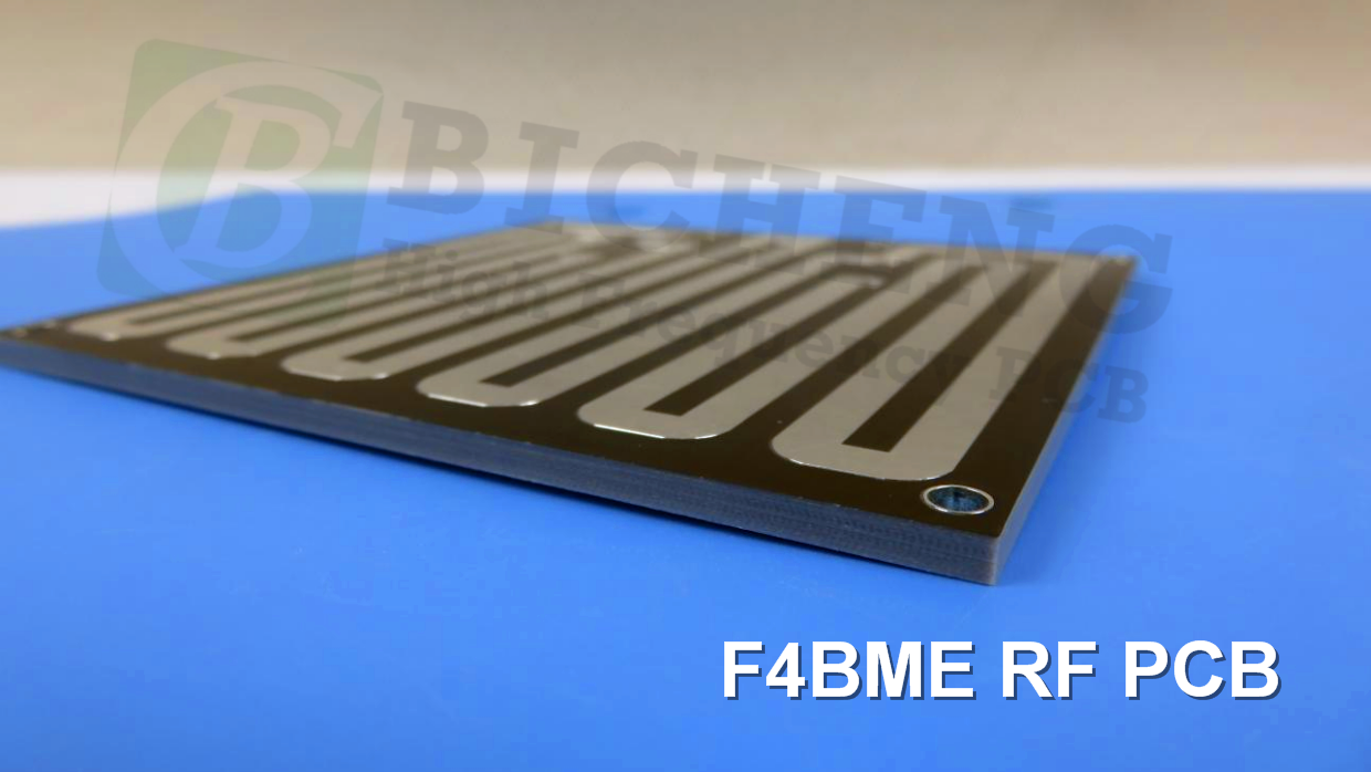
A PCB and Typical Applications
Displayed on the screen is a 2-layer copper high-frequency PCB with a low DK of 2.2, utilizing F4BME material and HASL surface finish on a 3.0mm substrate. |
|
|
|
|
|
F4BME high-frequency PCB finds applications in microwave, RF, and radar systems, as well as in phase shifters, passive components, power dividers, couplers, combiners, feed networks, phased array antennas, satellite communications, and base station antennas. |
|
|
|
|
|
|
|
|
|
|
|
Final - F4BME series aluminum-based/copper-based boards
These F4BME series of laminates can provide aluminum-based or copper-based materials, where one side of the dielectric layer is covered with copper foil, and the other side is covered with either aluminum-based material or copper-based , serving as shielding or heat dissipation purposes. |
|
|
|
|
|
Model examples
F4BME225-CU represents F4BME225 with an copper-based substrate. |
|
|
|
|
|
|
|